The throttle trim lever is only active when the flight mode
switch is in the normal position. Use the throttle trim to
increase or decrease the engine power when the flight
mode switch is in the Normal mode. The throttle trim lever
has no effect on flight modes 1, 2, 3, 4, or in throttle hold.
Note: Making changes to the throttle trim lever does
not change the input values for any of the points on
the throttle curve; it merely makes adjustments to the
engine idle speed position.
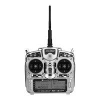
The Hovering Throttle lever increases or decreases the
engine output power for the middle three points set for
the throttle curve. As shown in the figure below, using
the hovering throttle lever shifts the curve upward or
downward parallel with the original curve. Therefore,
operation of the hovering throttle knob does not cause
any change to the original settings of the throttle curve.
The throttle trim range affects the throttle curve as shown.
The adjustable range of output using the hovering throttle
lever is approximately +/-15 points as shown in the
diagram below.
Note: The Hovering Throttle has no effect on flight
mode switch positions 1 and 2.
With the X9503 2.4 system, individual throttle curves
are selectable to be either straight (linear) or curved
(exponential) setting. With the exponential function on,
you will notice that any sharp angles of the throttle
curve will become more “rounded” or “smooth”,
creating more equal throttle servo movement during
the entire curve range.
Accessing the Throttle Curve Exponential
Function
1. From the Throttle Curve function, press the
Channel key until “EXP” appears at the center of the
LCD screen.
2. Highlight the EXP OFF with the Selector. Press the
Selector to change the display from OFF to ON.
3. To exit the Throttle Curve function, move the Selector
to highlight LIST and press.
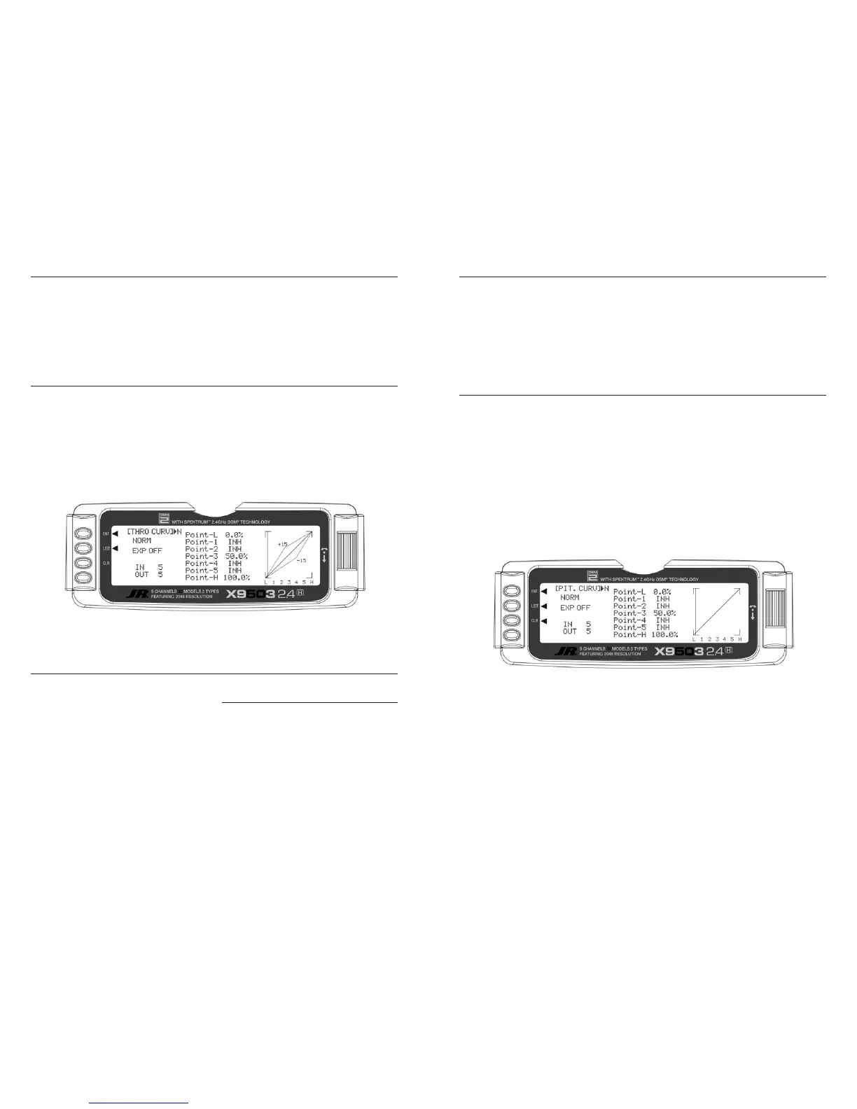
Adjustment of the pitch curve is very similar to the throttle
curve adjustment described in the preceding section. A
thorough understanding of the Throttle Curve Section will
make pitch curve adjustment easier to understand. There
are up to six independent types of pitch curves available:
Normal, Stunt-1, Stunt-2, Stunt-3, and Stunt-4 (Stunt 3
and 4 optional) and Hold. Each pitch curve contains up to
seven adjustable points: L, 1, 2, 3, 4, 5, and H.
Note: You can only set the pitch curve for the
Throttle Hold function and Stunt Modes 3 and 4, if
you previously activated them in the System mode.
INH for points 1, 2, 4 and 5. These values are
16.5%, 33%, 66.5% and 83.5% respectively if no
value changes are made to any other points. If you
change any of the other points while these points
are inhibited, the inhibited points change to plot a
smooth curve.
1. Turn the transmitter ON.
2. Press the LIST key to enter the Function mode.
3. Use the Selector to highlight the PIT. CURV function,
and press the to access.
Note: The Letter, numbers directly to the
right of PIT. CURV at the top right portion of
the LCD is the current flight mode switch position.
(N, 1, 2, 3, 4 or H).
Use NORMAL for hover curves and 1 through 4 (3 and
4 optional) for stunt curves. This example shows the
hovering curve.
4. Highlight the desired Pitch point to be adjusted. Press
the Selector to open the point value, then roll the
Selector to increase and decrease the point value.
5. To set curves for flight mode switch position 1,
highlight NORM with the Selector, press,
then select ST-1 from the drop down box
and repeat steps 4 and 5.
6. To set curves for flight mode switch positions 2
through 5, repeat step 6 above.
7. To exit the Pitch Curve function, highlight the LIST with
the Selector, and press.
Note: In each curve, the factory setting indicates
To keep this from happening, highlight each point and
press the Selector twice to activate each of the points.
Repeat as necessary. You can fully adjust the values for
these points with the Selector. To inhibit the points,
highlight the desired point with the Selector, press the
Selector to open the point, then press the clear key
(CLR) to inhibit.
 Loading...