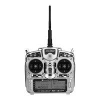
In FUNC.LIST highlight TRVL ADJ. Press the Selector
to access the Travel Adjust menu. Highlight the desired
channel then press the Selector to change the sub-trim
value of that channel. Moving the applicable control stick
or switch changes the direction in
In
FUNC.LIST highlight Butterfly. Press the Selector
to access the Butterfly menu. Note the default setting for
offset is at +170%. With this setting, the flap’s neutral
position (trailing edge level) occurs when the spoiler stick
is in the full up position. Highlight
SW select and press
the Selector to access the available switches. Rotate the
Selector to select the
BTF switch and press the Selector
to move the switch to Pos0. Be sure all switches in this
screen are set at zero. This is necessary to allow the
Butterfly function to always be on. Highlight SPOIFLAP
0
then depress the Selector to access the spoiler-to-flap
value. Move the spoiler stick to the full down position and
adjust the value by rotating the Selector until the desired
down flap position is achieved. Press the Selector to
store the flap value then rotate the Selector to access the
SPOIFPRN 0 function. Depress the Selector to access
this value and with the spoiler stick in the low position,
adjust the flaperons (ailerons as flaps) to the desired
position. You may wish to adjust the SPOIELEV at
this time, however, there is a curve mix in P-mix 1 that
allows several points on a curve to be adjusted for flap-to-
elevator mixing covered in Step 15 below. Press the LIST
button to return to the Function Mode screen.
On most sailplanes, deploying flaps causes the aircraft
to pitch up. This pitching is non-linear and typically the
which the travel adjustment is made (right/ left,
up/down). Set the travel adjust for all functions except
flaps at this time. Press the LIST button to return to
the Function Mode screen.
airplane pitches up dramatically the first 25% of flap
travel but becomes less dramatic during the 25% through
50% range, and very little additional up pitching occurs
from 75 to 100% flaps. The X9503 2.4 incorporates a
preprogrammed curve mix that mixes the spoiler stick
(landing flaps) to the elevator.
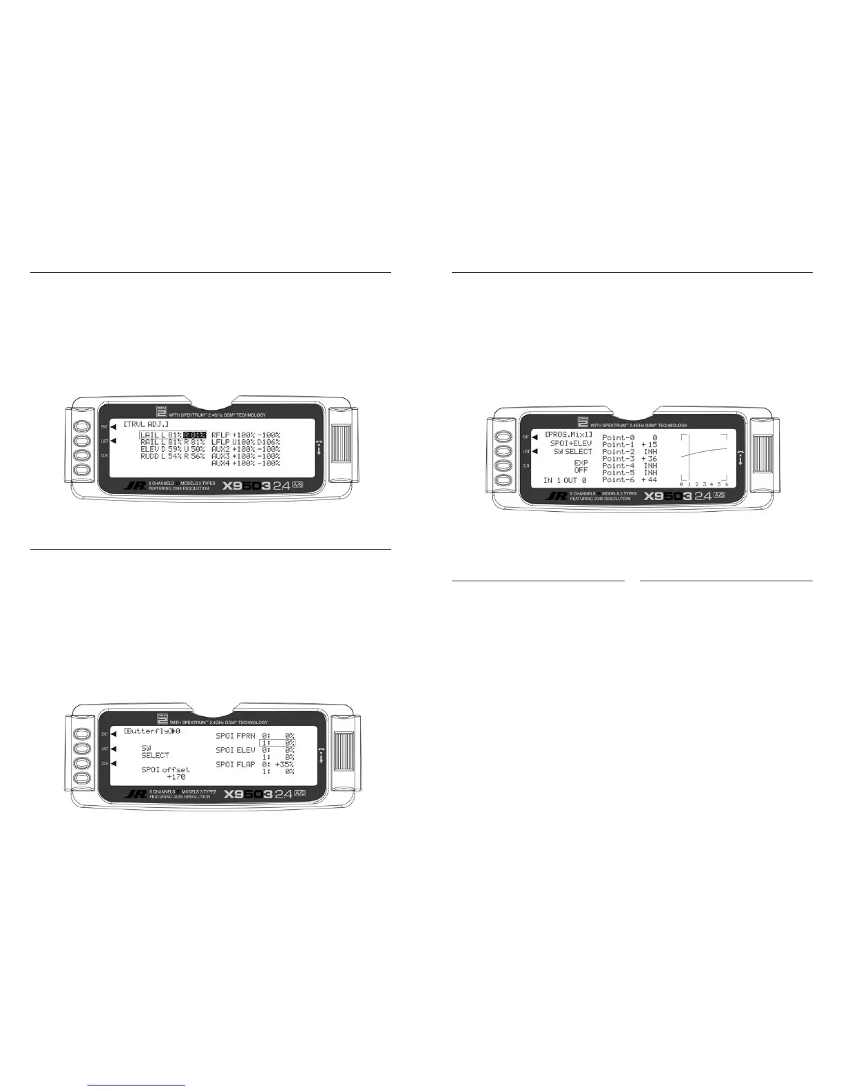
In
FUNC.LIST highlight PROG Mix1. Press the Selector
to access the Programmable mix 1 spoiler-to-elevator
curve mix. Highlight the desired point then press the
Selector to access the point’s value. Rotate the Selector
to change the value. You can adjust all points on the curve
using this method. The curve below shows the typical
values needed for a common performance sailplane. Press
the LIST button to return to the Function Mode screen.
Setting Up Flight Modes
Up to this point we have established the foundational
programming common to all flight modes. Now we will
focus on the specifics of setting up each individual flight
mode.
We will individually program the following parameters for
each of the selected flight modes (Launch, Cruise, Land).
• Dual and Exponential rates for Aileron, Elevator
and Rudder
• Preset positions for the Camber, Flaperon and
Elevator
• Elevator-to-Flap Mixes
• Aileron-to-Flap Mixes
• Aileron Differential
• Flight Mode Delay
• Camber Adjustment
• Aileron-to-Rudder Mixes
• Spoiler-to-Elevator Curve Mix (elevator
compensation)
Launch Mode Setup
In Step #8, Establishing Flight Modes, flight modes are
programmed to operate from the left front 3-position
switch. To select Launch mode, move the left 3-position
switch in the up position. In the main (info) screen
LAUNCH appears in the upper portion of the display when
Launch mode is selected. When making programming
changes/adjustments in Launch mode, this 3-position
switch must remain in the upper position during the
process to allow the results of those adjustments to be
seen on the model.
 Loading...