• Eliminate Pitch to Collective Trim Changes
(non CCPM only)
Use this when the Heli rolls left or right, or pitches
fore or aft when a collective input is given. This is
commonly caused by a mechanical geometry issue
in the design of the servo linkages and mechanical
mixers/levers. By using a program mix for Pitch-to-
Aileron to correct an Aileron trim change issue, the
mix allows the Aileron servo to move slightly in the
opposite direction of the out of trim direction in order
to keep the helicopter from rolling, while Collective
pitch is added or reduced. This standard mixer
designates the Pitch (Collective) as the Master and the
Ailerons as the Slave. For this type of Mix, you would
use Standard Program Mixes 3 through 6.
• Activating Retractable Gear via the Flight
Mode switch
This form of mix allows you to activate your retractable
landing gear via your Flight mode switch. It could be
set so that in Normal (Hover) and Throttle Hold (Hold)
modes, the retracts would be down, and when you
move the Flight Mode switch to positions 1 or 2, the
retracts would automatically go up and stay up in these
modes until you return to Normal or Throttle Hold. This
type of mix reduces the workload on you, so you can
focus on flying your model. This type of mix uses Multi
-Point Programmable mixes 1 or 2, and designates
FMOD (Flight Mode switch) as the Master and Gear or
another unused auxiliary channel as the slave.
The possibilities are endless and limited only by
the imagination.
The example below demonstrates a program mix for a heli
that pulls or climbs to the left when pulling vertical into a
maneuver such as a loop or stall turn. If you set up a mix
to provide a couple of degrees of Right aileron when up
Elevator is given, the aircraft then climbs vertically with no
change in Aileron tracking.
This mix uses the Elevator as the Master and the Aileron
as the Slave. You can turn it on and off via the Flight
Mode switch, so you can activate the mix only in the flight
modes where the trim change is noted, most commonly
forward flight modes 1–4 only.
Select and set the mix parameters in the following order:
Program Mix number (3-6), Master and Slave channels,
Mix Position and Flight Mode. This is generally a good
sequence to follow when setting up a Programmable Mix.
In this situation, the Offset value would remain at 0% (1/2
Stick).
Highlight and select one of the Standard Programmable
Mixers (PROG.MIX3PROG.MIX6) to obtain the first
Programmable Mix display. Then press ACT next to
CLR or highlight and select INH to obtain the main mix
display. The example is using PROG.MIX3.
1. Select Master. All Programmable Mixers default
to Throttle as both the Master and the Slave
(THROTHRO). The first THRO is the Master and
the second THRO represents the Slave. Since the
Elevator is the Master in this example, highlight the
first channel with the Selector and select ELEV to the
left of the arrow.
2. Select Slave. Highlight and select THRO to the right
of the arrow to obtain a list of channels that can be the
Slave. Highlight and select AILE as the Slave.
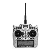
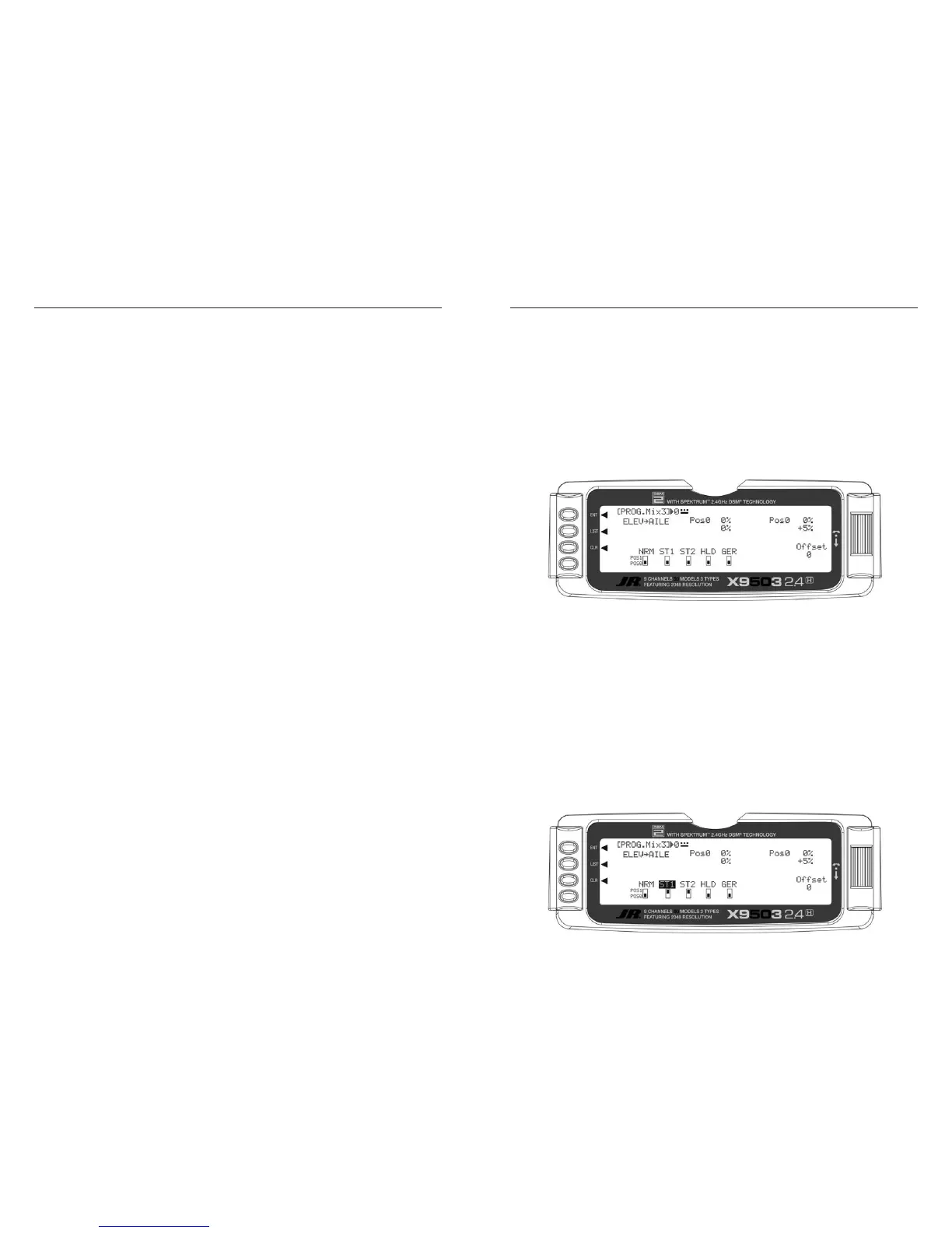
3. Select Position and Flight Modes. Move the Selector
to highlight each of the active flight modes (NRM,
ST1,ST2, ST3, ST4, GER, then select the mix position
(0 or 1) to be used. Since the mix value will be in
position 1, the flight modes where the mix would not
be required would be set to the POS 0 mix position
(will be left at 0%).
The number will change from 0 to 1 as the switch is
moved back and forth. When the number is 0, the mixer
looks at the Pos0 values (not programmed yet) and when
it is a 1 it looks at the Pos1 values (also not programmed
yet). For this example, assume this mix will be used in
Stunt Modes 1 and 2 only.
 Loading...