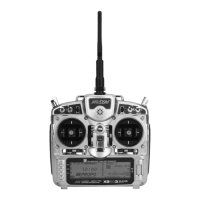
5. Set Points for Travel and Direction. There are
7 points along the travel of the Rudder (the line
intersected by the vertical line that moves right and
left with the Rudder stick). At each point an Elevator
deflection may be defined. A point that is set to 0%
represents no Elevator deflection at that point. A
negative value at a point typically indicates Up Elevator
movement while a positive value results in Down
Elevator movement. A point set to INH takes on the
value of the curve/line between the 2 adjacent points.
The direction of travel may be reversed (Up Elevator vs.
Down Elevator) by changing values from negative (-) to
positive (+) (moving the point values above and below
the 0% line).
Since the aircraft pitches to the landing gear with the
application of both Right and Left Rudder, the Elevator
deflection will be zero at center (Point-3) (no mixing).
At the points either side of Point-3 will be negative,
indicating Up Elevator movement. The more negative
a point value, the more Up Elevator deflection. Set the
points initially to the following values.
Point-0
- 10% (At full Right Rudder the Elevator will deflect
Up 10%)
Point-1
INH (Takes on the value along the curve between
Point-0 & Point-2)
Point-2
-3% (Elevator deflects Up 3% when Rudder is
moved to Point-2)
Point-3
0% (no Mixing – no Elevator deflection when
Rudder is at neutral)
Point-4
-3% (Elevator deflects Up 3% when Rudder is
moved to Point-4)
Point-5
INH (Takes on the value along the curve between
Point-4 & Point-6)
Point-6
-10% (At full Left Rudder the Elevator will deflect
Up 10%)
6. Offset. Point-3 represents the offset position and
corresponds to the Rudder stick being at neutral. It is
important to leave Point-3 set at 0% to make sure there
is no mixing and therefore no Elevator deflection when
the Rudder is at neutral.
7. Verify Operation. Turn the Receiver on and turn the
mix on using the Gear switch. Move the Rudder stick
from full right to full left. The Elevator should deflect
Up when the Rudder is moved in both directions. If
it moves down instead, change the percentages to
(+) values instead of (-) values at each point. If the
Elevator appears to be moving too much, reduce the
point values (less negative). If the Elevator does not
seem to move enough, then increase the point values
(more negative). Now turn the Gear switch to the OFF
position and verify that the Elevator does not move.
While test flying the aircraft, make note of the mixing and
whether it generates enough up-Elevator during knife-
edge to stop it from pitching to the gear, or generating
too much Elevator input, causing it to pitch to the canopy
instead of the gear. Also note the approximate position of
the Rudder stick when pitching occurs. Land the aircraft
and adjust the points closest to the position of the Rudder
stick when pitching occurs for more or less Elevator
deflection until the aircraft no longer pitches during knife-
edge. More negative generates more Up Elevator and less
negative generates less Up Elevator. Points 1 and 5 may
be activated and their value changed if necessary to fine-
tune the mix.
Note: To completely disable or otherwise
inhibit a mixer, highlight either the Master or
Slave and press the CLR button.
The X9503 2.4 contains a Trainer System that allows
the instructor to transfer some or all of the primary
flight control functions (Throttle, Aileron, Elevator and
Rudder) to the student. It also allows you to indicate if the
transmitter is the Master (controlled by the instructor) or
Slave (controlled by the student). The Snap Roll button
transfers control to the student when the X9503 2.4 is
being used as the Master/Instructor transmitter.
All Dual rates and Exponential settings in the Master
transmitter are transferred to the Slave transmitter when
the master transmitter channels are selected individually
in the trainer menu. The Slave transmitter battery must be
charged.
1. Connect the Trainer cord between the Master and
Slave transmitters. Turn the power on to the Master
transmitter. (The Slave transmitter remains powered off
and can even have the module removed if equipped
with a module)
2. Make sure the Slave transmitter is in the PPM/FM
modulation mode. If the slave system is a X9503 2.4,
or any other system that is Spread Spectrum only, such
as other JR 2.4GHz or Spektrum systems, this does not
apply.
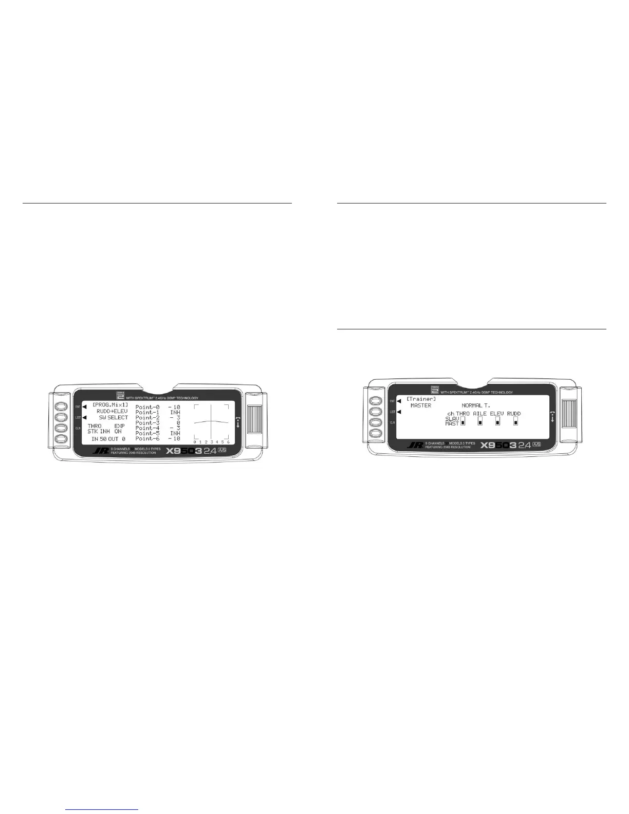
3. Highlight and select Trainer in the FUNC.LIST to
obtain the Trainer Display.
1. If the X9503 2.4 is the Master transmitter select the
channel(s) operated by the Slave transmitter when the
trainer switch is depressed.
When all channel selectors are in the MAST position,
NORMAL appears on the display and all 4 channels
are transferred to the student when the trainer switch is
depressed. When all channel selectors are in the MAST
position, the slave system must be programmed for the
model, meaning all programming necessary for the model
must be programmed in both the master and the slave
systems. Also when all the channel selectors are in the
MAST position, the slave system should be left in normal
default MASTER mode.
To transfer only certain channels to the student, highlight
and select the channels you will transfer, moving the
indicator for these channels to the SLAV position for
these channels. When less than all channels are selected
as SLAV, PROGRAM T appears on the display
indicating that the Trainer System has been programmed
to transfer only selected channels. When the channel
selectors are in the SLAV position, all programming of the
master system will be used, and only the stick movements
of the 4 primary channels are used from the slave system
when control is given to the slave transmitter. In this case,
the slave system does not need to be programmed for the
model. Also the slave system should be set to Slave mode
in it’s trainer system.
The X9503 2.4 is now ready to be used as the Master
or instructor transmitter. Depress the Snap Roll button
to transfer control to the student. Control will remain
transferred until the Snap Roll button is released.
 Loading...