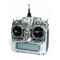
Advanced Digital Trims
TheX95032.4featuresAdvancedDigitalTrims.Onthe
Normal display screen, if a trim lever is moved, the screen
will automatically change to display the graphic position
forthetrimbeingadjusted.TheX95032.4’sAileron,
Elevator,andRuddertrimleversfeatureanaudiblecenter
trimbeep.Thisishelpfulindeterminingthetrimlevers’
center position during flight. In addition, the frequency of
eachtrimstepchangesfromfullright/uptofullleft/down,
allowing the pilot to be aware of the general trim position
audibly without looking at the transmitter.
ByusingtheTrimStepFunctionlocatedintheSystem
Mode, you can adjust the amount of travel per each trim
step for your specific application.
Please note, when you turn it off, the X9503 stores the
trim values in memory and recalls them when turned back
on.
Use a 2mm Allen wrench to unlock the setscrew to adjust
thesticklength.Turnthewrenchcounterclockwiseto
loosenthescrew.Then,turnthestickclockwisetoshorten
or counterclockwise to lengthen the overall stick length.
After the control stick length has been adjusted to suit your
flying style, tighten the 2mm setscrew. If you desire longer
sticks, JR offers a stick (JRPA047) that is approximately
one inch longer than standard, and has various length
anodized aluminum stick ends available (JRPA040-
JRPA045).Thesestickendsarecraftedfrombarstock
aluminum, and are available at your local JR dealer.
An eyelet provided on the face of the X9503 transmitter allows
youtoconnectaNeckStrap(JRPP607).Neckstrapadaptors
are also available to customize the balance of the transmitter
(JRPA140-JRPA142andSPM6703).
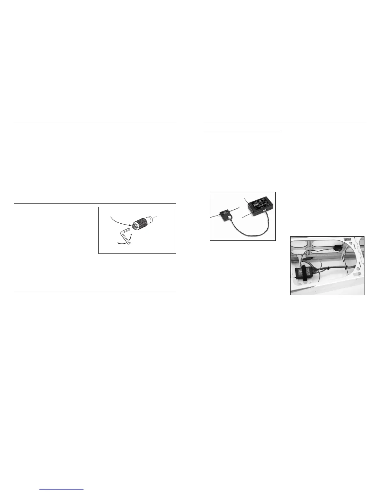
Installing the JR R921
TheJRR921incorporatesdualinternalreceivers,andone
or two remote receivers offering the security of up to four
simultaneous RF links for the ultimate in multi-path RF
security.ThemainPCboardhastwointernalreceivers,
while a third remote receiver must be plugged into one
of the antenna ports in order for the system to operate.
Optionally, you can plug a second remote receiver into
the remaining remote antenna port giving a total of four
operationalreceivers.Bylocatingthesereceiversin
different locations throughout the aircraft, each receiver
is exposed to its own RF environment, greatly improving
path diversity.
Note:TheJRR921requiresatleastoneremote
receiver be used.
Install the main receiver using the same method you
would use to install a conventional receiver in your
aircraft.Typicallywrapthemainreceiverinprotective
foam and fasten it in place using rubber bands or hook
and loop straps. Alternately in electric models or in jets
(low vibration), it’s acceptable to use thick double-sided
foam tape to fasten the main receiver in place.
Mounting the remote receiver(s) in a different
location(s) from the primary receiver, gives tremendous
improvementsinpathdiversity.Essentiallyeachreceiver
sees a different RF environment and this is the key to
maintaining a solid RF link, even in aircraft that have
substantial conductive materials, (e.g. turbine engines
with metal tail pipes, carbon fiber, tuned pipes, etc.) which
can weaken the signal.
Using double-sided foam tape, (servo tape) mount the
remote receiver(s) keeping the remote antenna(s) at least
2 inches away from the primary antenna. Ideally the
antennas will be oriented perpendicular to each other;
however,we’vefoundthistonotbecritical.6-inch,
9-inch,12-inch,24-inchand36-inchleadsareavailable
and in sophisticated aircraft, we’ve found it best to mount
the remote receivers in different parts of the aircraft
keeping the remote antennas as far away as practical from
any conductive materials. A typical installation would
include the main receiver mounted in the conventional
location in the fuselage and the remote antennas in the
nose(jets)inthetopturtledeckandeveninthetail.The
optimum location is as far away from any conductive
materials as practical.
LOOSEN
TIGHTEN
SETSCREW
 Loading...