8 Optional equipment
8.1
Sideshifter / Fork positioner (o)
WARNING!
A faulty attachment can be hazardous
Check the attachment daily for external signs of damage or defects. Faulty
attachments can cause the load to fall.
u
Report any defects immediately to your supervisor.
u
Tag out and decommission a faulty lift truck.
u
Only return the truck to service when you have identified and rectified the fault.
Z
Maintenance intervals are specified in the section Maintenance, Inspection and
Changing of Maintenance Parts Requiring Replacement, see page 357.
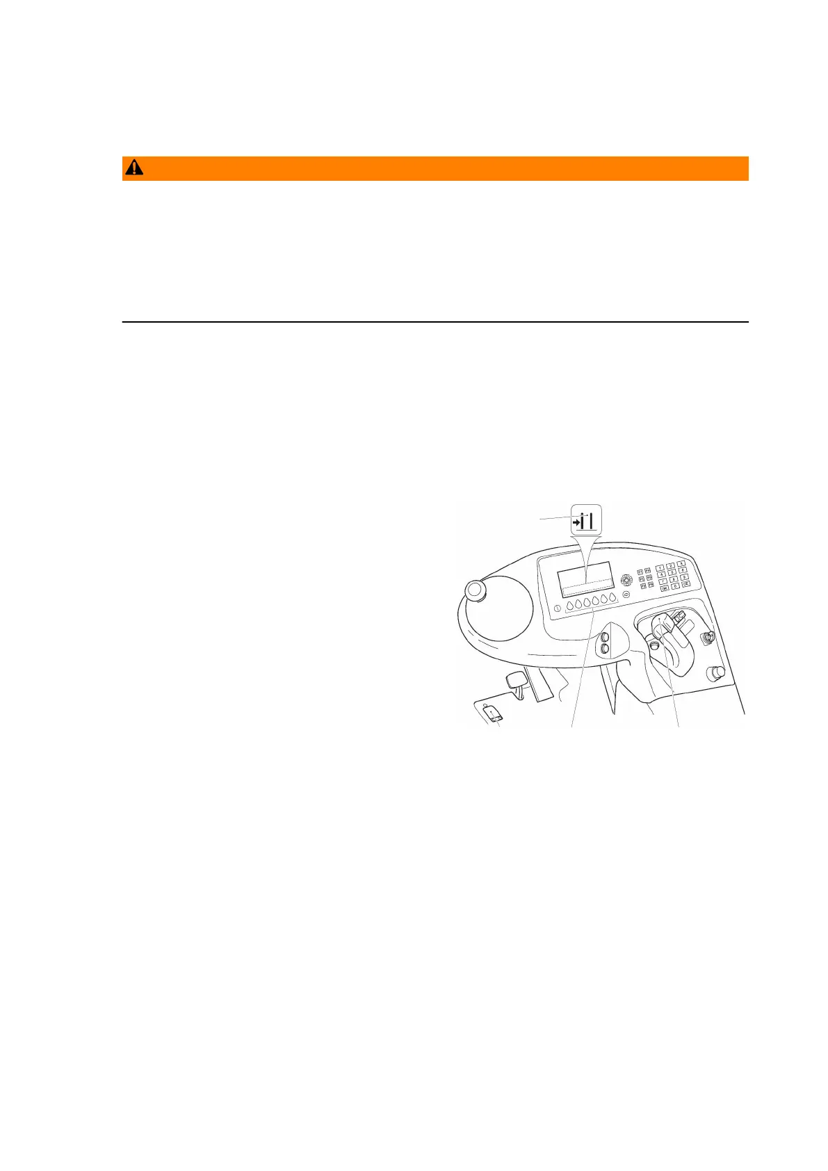
8.1.1
Fork sideshift (o)
Requirements
– Prepare the truck for operation, see page 138 or see page 139.
Procedure
• Do not press the dead man's switch (20).
• Press and hold down the key (104)
under the "fork sideshift" symbol (194).
• Attachment is in the "front lift" position,
i. e. the forks are at right angles to the
swivel traverse frame:
• To shift the forks to the right:
Turn the "hydraulic functions" control
lever (113) clockwise.
• To shift the forks to the left:
Turn the "hydraulic functions" control
lever (113) anticlockwise.
• Attachment is in the right-hand home position, i. e. the fork carriage is at the right
end of the swivel traverse frame and the forks are facing left:
• To shift the forks in the load direction:
Turn the "hydraulic functions" control lever (113) clockwise.
• To shift the forks in the drive direction:
Turn the "hydraulic functions" control lever (113) anticlockwise.
• Attachment is in the left-hand home position, i. e. the fork carriage is at the left
end of the swivel traverse frame and the forks are facing right:
• To shift the forks in the drive direction:
Turn the "hydraulic functions" control lever (113) clockwise.
• To shift the forks in the load direction:
Turn the "hydraulic functions" control lever (113) anticlockwise.
Z
The traverse speed of the forks is proportional to the movement of the "hydraulic
functions" control lever (113).
Both forks move evenly in the prescribed direction.
247
04.19 en-GB
 Loading...