To connect and configure the switch by using the J-Web interface:
1. Transition the switch into initial setup mode:
•
EX2200 and EX2200-C switch—Press the mode button located on the lower right
corner of the front panel for 10 seconds.
•
EX3200, EX3300, EX4200, EX4300, EX4500, EX4550, EX6200, or EX8200
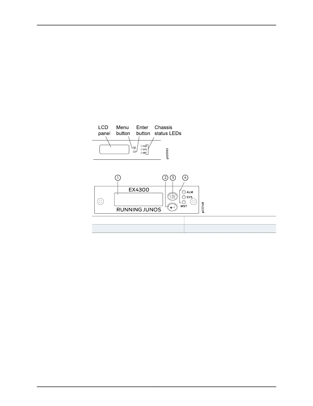
switch—Use the Menu and Enter buttons located to the right of the LCD panel (see
Figure 67 on page 184 or Figure 68 on page 184):
Figure 67: LCD Panel in an EX3200, EX4200, EX4500, EX4550, or EX8200
Switch
Figure 68: LCD Panel in an EX4300 Switch
3—1— LCD panel Menu buttonLCD panel
4—2— Chassis status LEDsLCD panel Enter button
1. Press the Menu button until you see MAINTENANCE MENU. Then press the Enter
button.
2. Press Menu until you see ENTER EZSetup. Then press Enter.
If EZSetup does not appear as an option in the menu, select Factory Default to
return the switch to the factory default configuration. EZSetup is displayed in
the menu of standalone switches only when a switch is set to the factory default
configuration.
3. Press Enter to confirm setup and continue with EZSetup.
2. Connect the Ethernet cable from the Ethernet port on the PC to the switch.
•
EX2200, EX3200, or EX4200 switch—Connect the cable to port 0 (ge-0/0/0) on
the front panel of the switch.
•
EX3300, EX4500, or EX4550 switch—Connect the cable to the port labeled MGMT
on the front panel (LCD panel side) of the switch.
•
EX4300 switch—Connect the cable to the port labeled MGMT on the rear panel of
the switch.
Copyright © 2017, Juniper Networks, Inc.184
EX2300-C and EX2300 Switches Hardware Guide