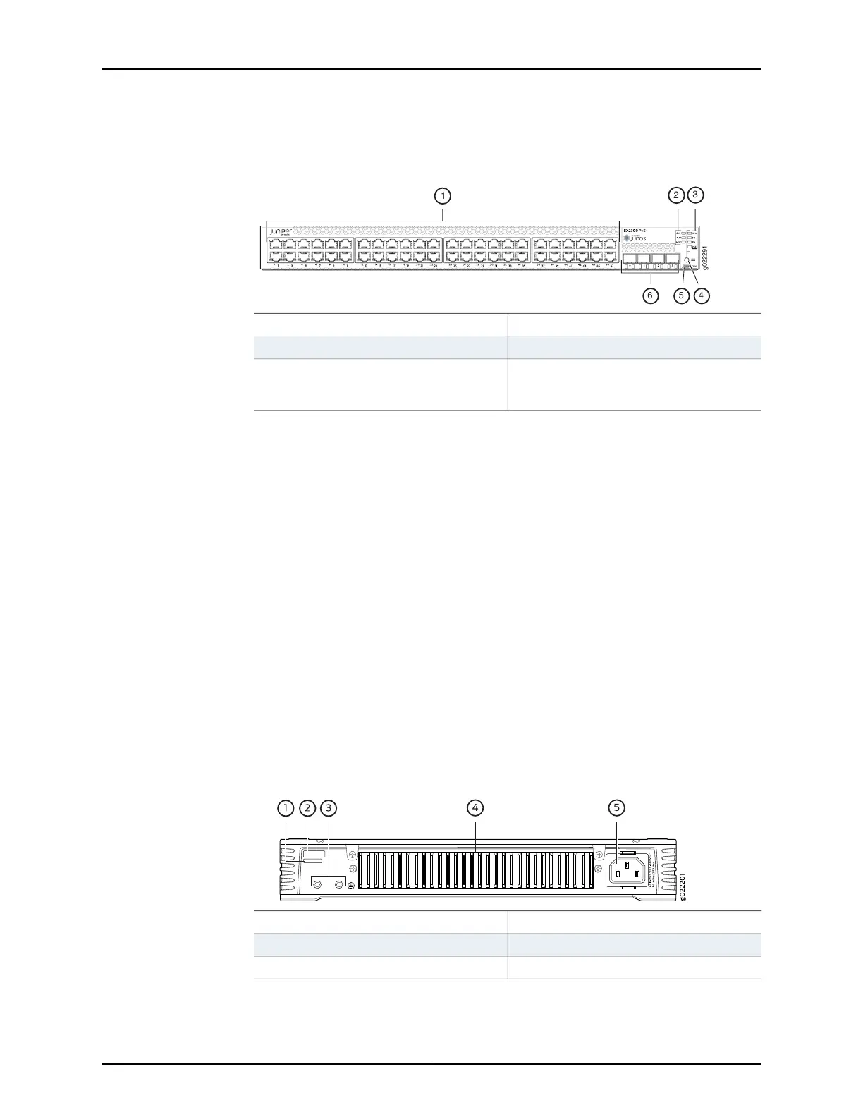
Figure 4: Front Panel of an EX2300 Switch with 48 Gigabit Ethernet Ports
with PoE Capability
4—1— Factory Reset/Mode buttonRJ-45 network ports
5—2— Mini-USB console portChassis status LEDs
6—3— 10-Gigabit Ethernet uplink portsPort status mode LEDs. The LED labeled
PoE is present only on models with PoE
capability.
Rear Panel of an EX2300 Switch
The rear panel of an EX2300-C switch consists of the following components:
•
Serial number ID label
•
CLEI code label
•
One protective earthing terminal
•
Heatsink
•
One AC power cord inlet
Figure 5 on page 8 shows the rear panel of an EX2300-C switch with 12 Gigabit Ethernet
ports with PoE capability and Figure 6 on page 9 shows the rear panel of an EX2300-C
switch with 12 Gigabit Ethernet ports without PoE capability.
EX2300-C switches being fanless models have no exhaust openings. EX2300 switches
have vents on the top of the chassis. The PoE models have a heatsink installed in the
rear panel to dissipate heat, while non-PoE models have no heatsink.
Figure 5: Rear Panel of an EX2300-C Switch with 12 Gigabit Ethernet Ports
with PoE Capability
4—1— Heatsink—only in PoE modelsCLEI code label
5—2— AC power cord inletSerial number ID label
3—Protective earthing terminal
Copyright © 2017, Juniper Networks, Inc.8
EX2300-C and EX2300 Switches Hardware Guide