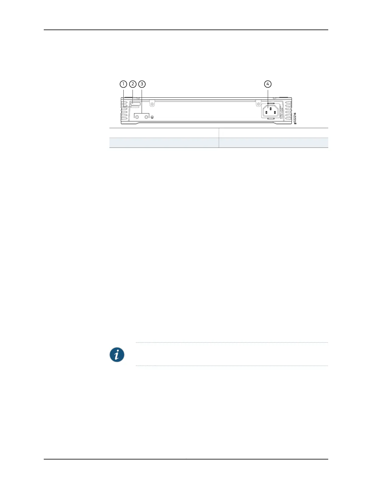
Figure 6: Rear Panel of an EX2300-C Switch with 12 Gigabit Ethernet
Ports without PoE Capability
3—1— Protective earthing terminalCLEI code label
4—2— AC power cord inletSerial number ID label
The rearpanel of the EX2300 switch except the EX2300-C switch consistsof the following
components:
•
One management Ethernet port that supports an RJ-45 connector
•
One console port that supports an RJ-45 connector
•
One protective earthing terminal
•
One ESD point
•
Air exhaust openings
•
Serial number ID label
•
CLEI code label
•
One AC power cord inlet or DC power terminals
•
One USB port
Figure 7 on page 10 shows the rear panel of an AC-powered EX2300 switch with 24
Gigabit Ethernet ports with PoE capability and Figure 10 on page 11 shows the rear panel
of an EX2300 switch with 48 Gigabit Ethernet ports with PoE capability.
Figure 8 on page 10 shows the rear panel of an AC-powered EX2300 switch with 24
Gigabit Ethernet ports without PoE capability and Figure 11 on page 11 shows the rear
panel of an EX2300 switch with 48 Gigabit Ethernet ports without PoE capability.
Figure9 on page 10 shows the rear panel of a DC-powered EX2300 switch with 24 Gigabit
Ethernet ports.
NOTE: DC-powered EX2300 switches do not provide PoE.
The AC power cord retainer clips extend out of the chassis by 3 in (7.62 cm).
9Copyright © 2017, Juniper Networks, Inc.
Chapter 1: System Overview