•
Two built-in 10-Gigabit Ethernet uplink ports. You can use the uplink ports to forward
network traffic or configure them as VCPs to interconnect EX2300 switches into a
Virtual Chassis.
•
One electrostatic discharge (ESD) point
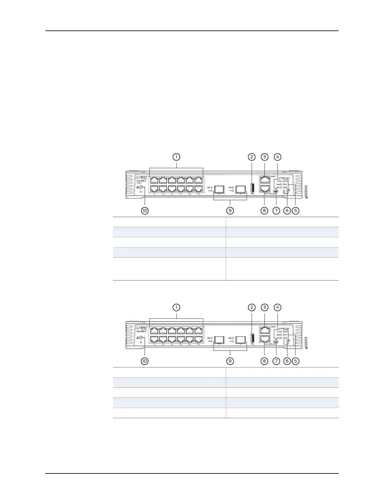
Figure 1 on page 6 shows the front panel of an EX2300-C switch with 12 Gigabit Ethernet
ports with PoE capability and Figure 2 on page 6 shows the front panel of an EX2300-C
switch with 12 Gigabit Ethernet ports without PoE capability.
Figure 1: Front Panel of an EX2300-C Switch with 12 Gigabit Ethernet
Ports with PoE Capability
6—1— Factory Reset/Mode buttonRJ-45 network ports
7—2— Mini-USB console portUSB port
8—3— RJ-45 console portManagement Ethernet port
9—4— 10-Gigabit Ethernet uplink portsChassis status LEDs
10—5— ESD pointPort status mode LEDs. The LED labeled
PoE is present only on models with PoE
capability.
Figure 2: Front Panel of an EX2300-C Switch with 12 Gigabit Ethernet
Ports without PoE Capability
6—1— Factory Reset/Mode buttonRJ-45 network ports
7—2— Mini-USB console portUSB port
8—3— RJ-45 console portManagement Ethernet port
9—4— 10-Gigabit Ethernet uplink portsChassis status LEDs
10—5— ESD pointPort status mode LEDs
Copyright © 2017, Juniper Networks, Inc.6
EX2300-C and EX2300 Switches Hardware Guide