•
Turn the screws only part way in, leaving about 1/4 in. (6 mm) distance between
the head of the screw and the wall.
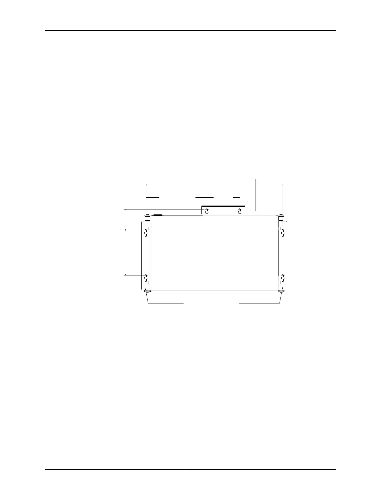
a. Install screw A.
b. Install screw B 18.68 in. (47.4 cm) from screw A on a level line.
c. Install screw C 5.98 in. (15.2 cm) on a plumb line down from screw A and screw D
5.98 in. down from screw B.
d. Install screw E 2.76 in. (7 cm) up from and 8.32 in. (21.1 cm) to the right of screw A.
e. Install screw F 4.49 in. (11.4 cm) to the right of screw E.
Figure 29: Measurements for Installing Mounting Screws
18.68 in. (47.4 cm)
Front
Rear
A
E F
C
B
D
Side wall-mount brackets
8.32 in. (21.1 cm)
4.49 in.
(11.4 cm)
5.98 in.
(15.2 cm)
2.76 in (7 cm)
g021211
Wall-mount baffle
5. Lift the unit (one switch or two) by grasping each side, and hang the unit by attaching
the brackets to the mounting screws as shown in Figure 30 on page 78.
6. Tighten all mounting screws.
77Copyright © 2011, Juniper Networks, Inc.
Chapter 9: Installing the Switch