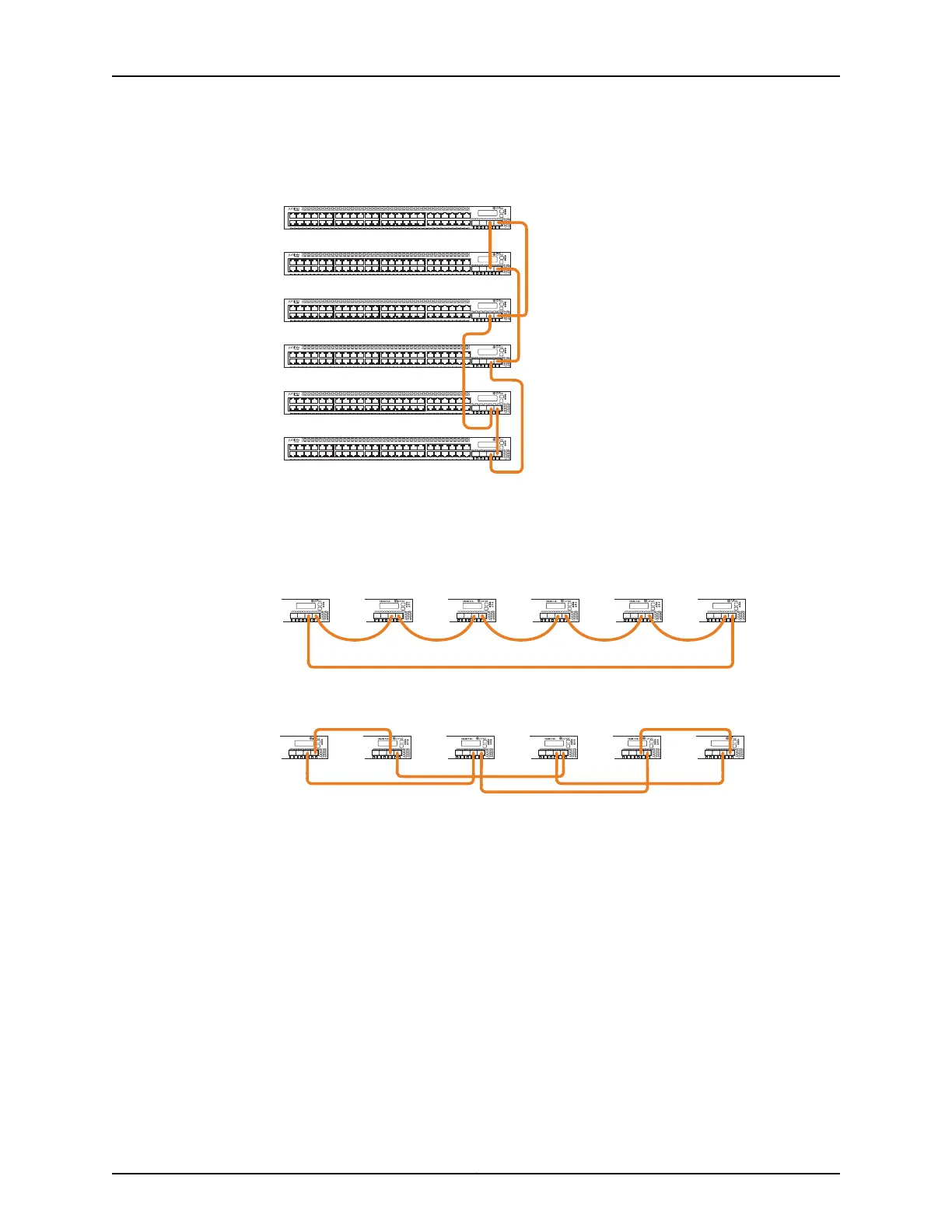
Figure 18: EX3300 Switches Mounted on a Single Rack and Connected in
a Ring: Option 3
g021234
0 1 2 3
ALM
EX3300 PoE+
SYS
MST
0 1 2 3
ALM
EX3300 PoE+
SYS
MST
0 1 2 3
ALM
EX3300 PoE+
SYS
MST
0 1 2 3
ALM
EX3300 PoE+
SYS
MST
0 1 2 3
ALM
EX3300 PoE+
SYS
MST
0 1 2 3
ALM
EX3300 PoE+
SYS
MST
Figure 19 on page 62 and Figure 20 on page 62 show six EX3300 switches mounted on
the top rows of adjacent racks and interconnected in a ring topology.
Figure 19: EX3300 Switches Mounted on Adjacent Racks and Connected
in a Ring Topology Using Medium and Long Cables: Option 1
0 1 2 3
ALM
EX3300 PoE+
SYS
MST
0 1 2 3
ALM
EX3300 PoE+
SYS
MST
g021235
Figure 20: EX3300 Switches Mounted on Adjacent Racks and Connected
in a Ring Topology Using Medium and Long Cables: Option 2
0 1 2 3
ALM
EX3300 PoE+
SYS
MST
0 1 2 3
ALM
EX3300 PoE+
SYS
MST
g021236
Related
Documentation
• Understanding EX3300 Virtual Chassis Hardware Configuration on page 59
• Understanding EX3300, EX4200, and EX4500 Virtual Chassis Components
• Planning EX3300 Virtual Chassis on page 60
Copyright © 2011, Juniper Networks, Inc.62
Complete Hardware Guide for EX3300 Ethernet Switches