Before mounting the switch on a wall:
•
Verify that the site meets the requirements described in “Site Preparation Checklist
for EX3300 Switches” on page 41.
•
Read “General Safety Guidelines and Warnings” on page 133, with particular attention
to “Chassis Lifting Guidelines for EX3300 Switches” on page 144.
Ensure that you have the following parts and tools available:
•
2 wall-mount brackets (provided in the wall-mount kit)
•
12 wall-mount bracket screws (provided in the wall-mount kit)
•
6 mounting screws (8-32 x 1.25 in. or M4 x 30 mm) (not provided)
•
Hollow wall anchors rated to support up to 75 lb (34 kg) if you are not screwing the
screws directly into wall studs (not provided)
•
Phillips (+) screwdriver, number 2
To mount one or two switches on a wall:
1. Remove the switch from the shipping carton (see “Unpacking an EX3300 Switch” on
page 66).
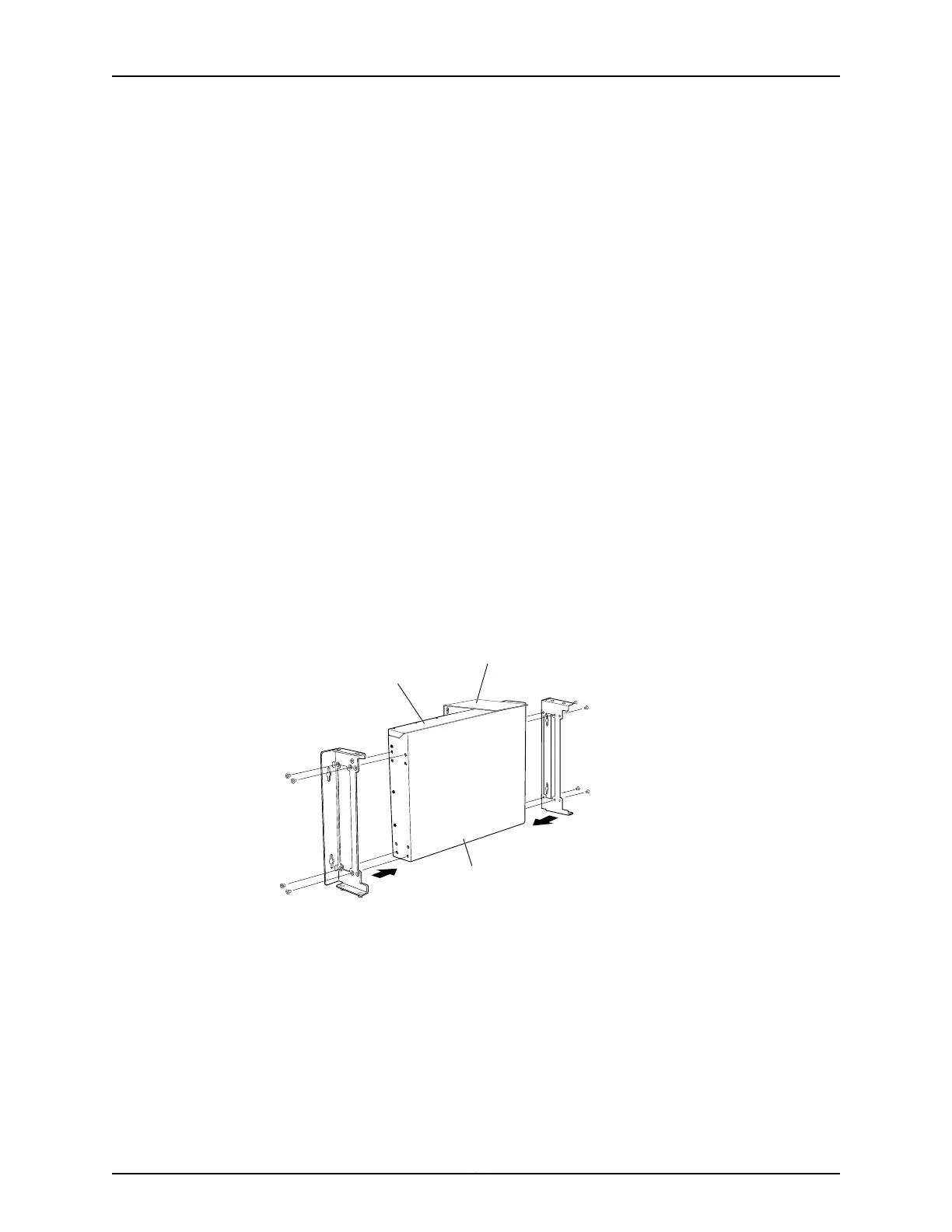
2. Attach the wall-mount brackets to the sides of the chassis using four wall-mount
bracket screws on each side, as shown in Figure 28 on page 76.
Figure 28: Attaching Wall-Mount Brackets to a Switch Chassis
g021213
Front panel
Rear panel
Wall-mount baffle
3. If you are mounting two switches together, align the second switch on top of the first
and attach it to the mounting brackets using two additional wall-mount bracket
screws on each side. (Figure 30 on page 78 shows two aligned switches.)
4. Install six mounting screws in the wall for the wall-mount brackets and baffle as
shown in Figure 29 on page 77:
•
Use hollow wall anchors rated to support up to 75 lb (34 kg) if you are not inserting
the mounting screws directly into wall studs.
Copyright © 2011, Juniper Networks, Inc.76
Complete Hardware Guide for EX3300 Ethernet Switches