EasyManuals Logo

Juniper EX3300 Series User Manual

Juniper EX3300 Series
202 pages
To Next Page IconTo Next Page
To Previous Page IconTo Previous Page
Page #73 background imageLoading...
Page #73 background image
Follow these clearance requirements:
Allow at least 6 in. (15.2 cm) of clearance on the side between devices that have fans
or blowers installed. Allow 2.8 in. (7 cm) between the side of the chassis and any
non-heat-producing surface such asa wall. For the cooling system to function properly,
the airflow around the chassis must be unrestricted.
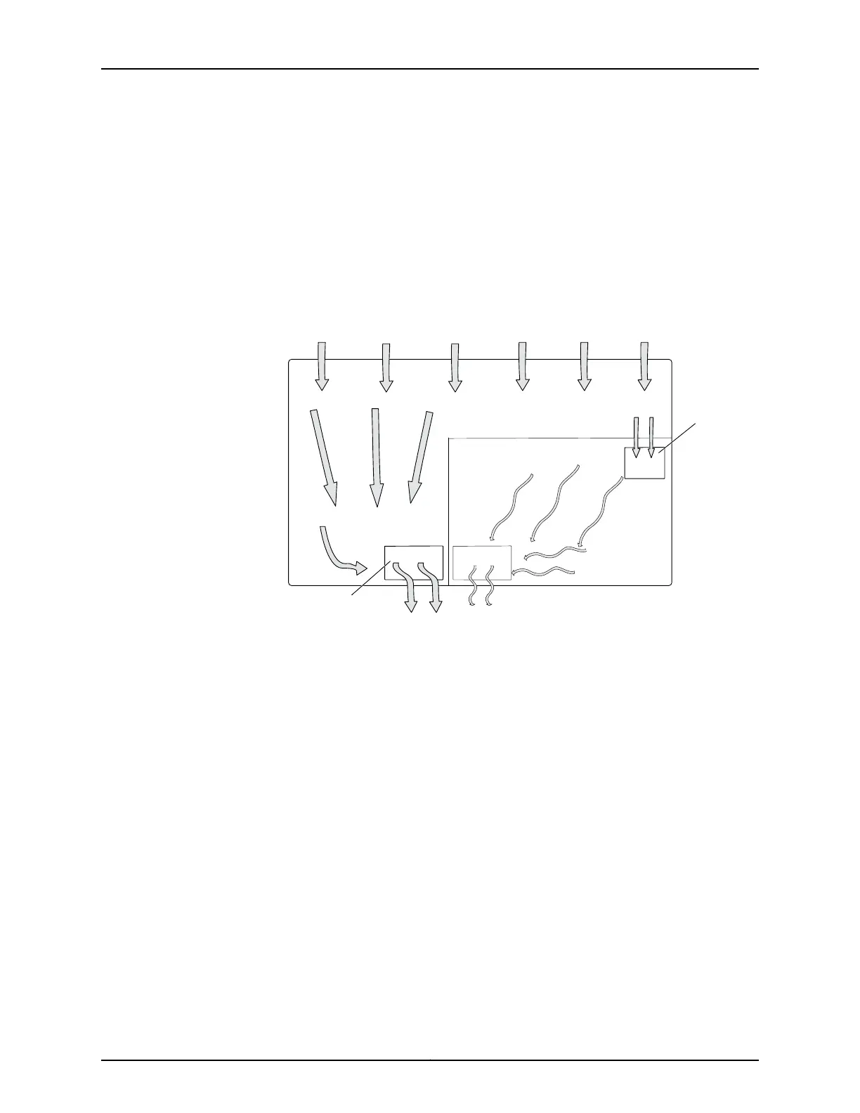
Figure 13 on page 51 shows airflow in a front-to-back airflow model.
Figure 13: Front-to-Back Airflow Through the EX3300 Switch Chassis
g021205
Chassis rear
Chassis front
Fan
Fan
Air intake
Fan air
exhaust
Air intake
Air exhaust
Figure 14 on page 52 shows airflow through a back-to-front airflow model.
51Copyright © 2011, Juniper Networks, Inc.
Chapter 5: Mounting and Clearance Requirements

Table of Contents

Questions and Answers:

Question and Answer IconNeed help?

Do you have a question about the Juniper EX3300 Series and is the answer not in the manual?

Juniper EX3300 Series Specifications

General IconGeneral
Layer SupportLayer 2 and Layer 3
JUNOS OSYes
Ports24 or 48 x 10/100/1000BASE-T ports
Uplink Ports4 x 1GbE/10GbE SFP/SFP+ ports
Power SupplyAC or DC options
StackingYes, up to 10 units
MAC Address Table Size32, 000
Operating Humidity10% to 90% non-condensing
PoE SupportAvailable on PoE models
Virtual ChassisYes, up to 10 units
Operating Temperature32° to 104° F (0° to 40° C)

Related product manuals