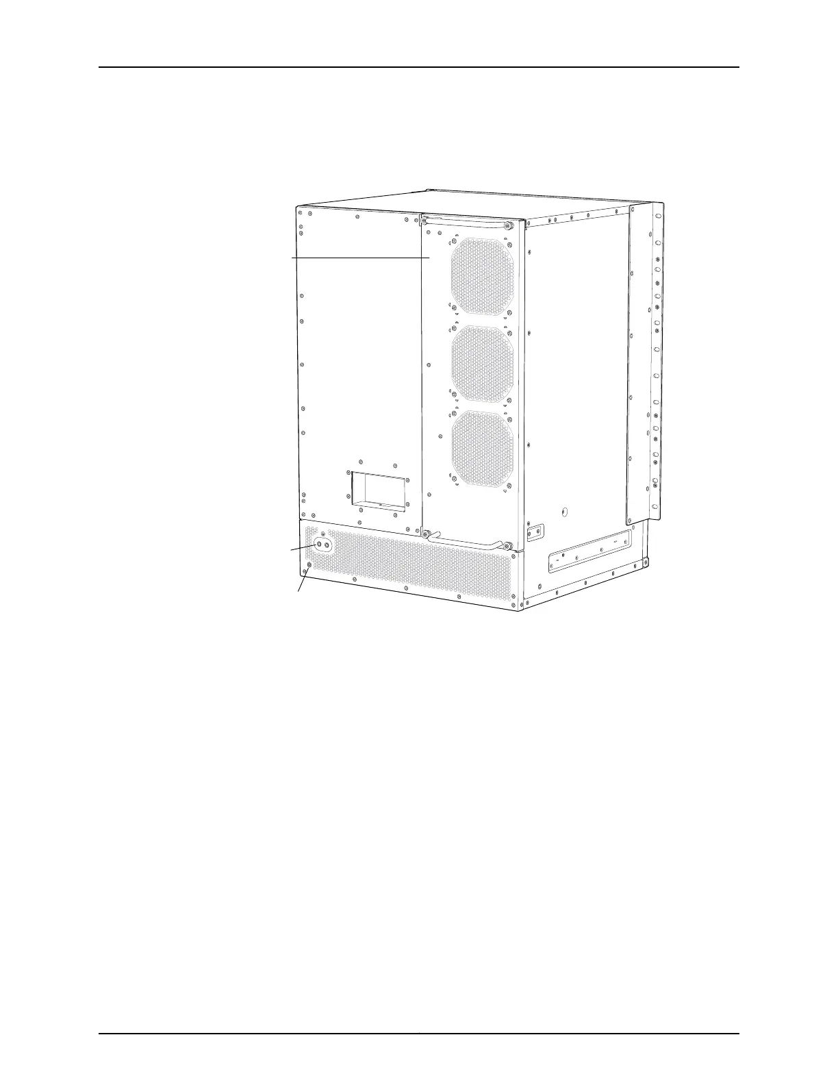
Figure 34: Location of Protective Earthing Terminal on an Ex6210 Switch
g021101
Earthing
terminal
Fan tray
ESD point
An AC-powered EX Series switch chassis gets additional grounding when you plug the
power supply in the switch into a grounded AC power outlet by using an AC power cord
appropriate for your geographical location. See AC Power Cord Specifications for an
EX6200 Switch.
Ensure that you have the following parts and tools available:
•
Grounding cable for your EX6210 switch (not provided)—The grounding cable must
be the same gage as the power feed cables and as permitted by the local code.
•
Grounding lug for your grounding cable (provided). See Grounding Cable and Lug
Specifications for EX6200 Switches.
•
Two ¼-20x0.5-in. screws and two flat washers to secure the grounding lug to the
protective earthing terminal (provided)
•
Phillips (+) screwdriver, number 2 (not provided)
To connect earth ground to an EX6210 switch:
Copyright © 2011, Juniper Networks, Inc.88
Complete Hardware Guide for EX3300 Ethernet Switches