• Installing and Connecting an EX3300 Switch on page 65
Front Panel of an EX3300 Switch
The front panel of an EX3300 switch consists of the following components:
•
Network ports:
•
Depending on the switch model, 24 or 48 10/100/1000BASE-T Gigabit Ethernet
ports (ports labeled 0 through 23 or 0 through 47)
•
Power over Ethernet Plus (PoE+) available in all network ports in EX3300-24P and
EX3300-48P models
•
Power over Ethernet Plus (PoE+) not available in any network port in EX3300-24T,
EX3300-24T-DC, EX3300-48T, and EX3300-48T-BF models
•
Four built-in uplink ports:
•
The uplink ports support 1-gigabit small form-factor pluggable (SFP) transceivers,
10-gigabit small form-factor pluggable (SFP+) transceivers, or a combination of
these transceivers.
•
Ports labeled 0 and 1 are, by default, configured as network ports. You can configure
these ports as Virtual Chassis ports (VCPs).
•
Ports labeled 2 and 3 are, by default, configured as VCPs. You can configure these
ports as network ports.
•
Network port and uplink port LEDs
•
Three chassis status LEDs
•
LCD panel and the LCD navigation buttons
•
Air intake or air exhaust, depending on the switch model—The intake or exhaust is
located immediately below the top edge of the front panel.
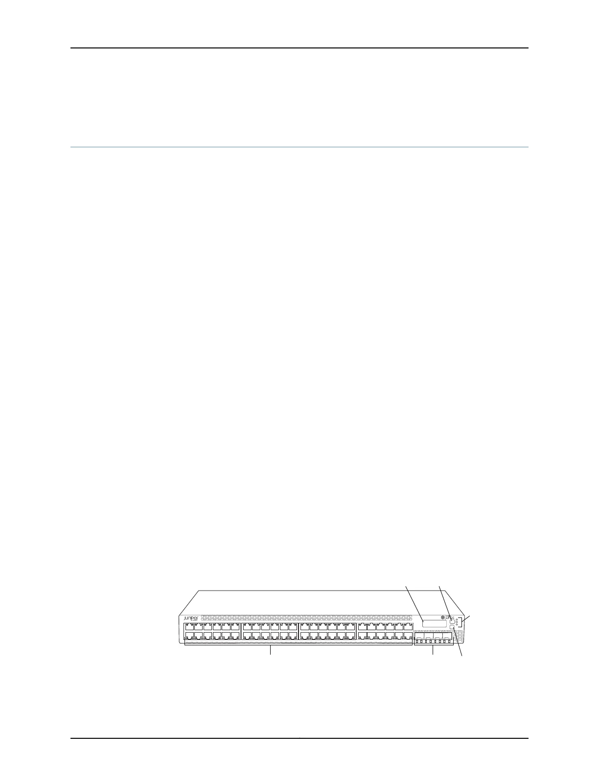
Figure 1 on page 6 shows the front panel of an EX3300 switch with 48 Gigabit Ethernet
ports. Figure 2 on page 7 shows the front panel of an EX3300 switch with 24 Gigabit
Ethernet ports.
Figure 1: Front Panel of an EX3300 Switch with 48 Gigabit Ethernet Ports
g021216
0 1 2 3
ALM
EX3300 PoE+
SYS
MST
LCD panel
Network ports
Chassis
status
LEDs
Enter buttonSFP+ uplink ports
Menu button
Copyright © 2011, Juniper Networks, Inc.6
Complete Hardware Guide for EX3300 Ethernet Switches