DCE80-100E
Technical Handbook
Main hydraulics
Description
4
P.Group 70
TDCE01
04GB
The other hydraulic pump delivers fluid to the other functions of
the main system and to the accumulator which in turn serves the
parking brake, driving brake and servo system of the control
levers (optional). All surplus fluid is supplied to the lifting function.
When the accumulator is fully charged and the lifting function is
deflected to maximum, the capacity of both pumps is utilized for
maximum lifting speed.
The fluid is cleaned through a high pressure filter upstream after
each pump.
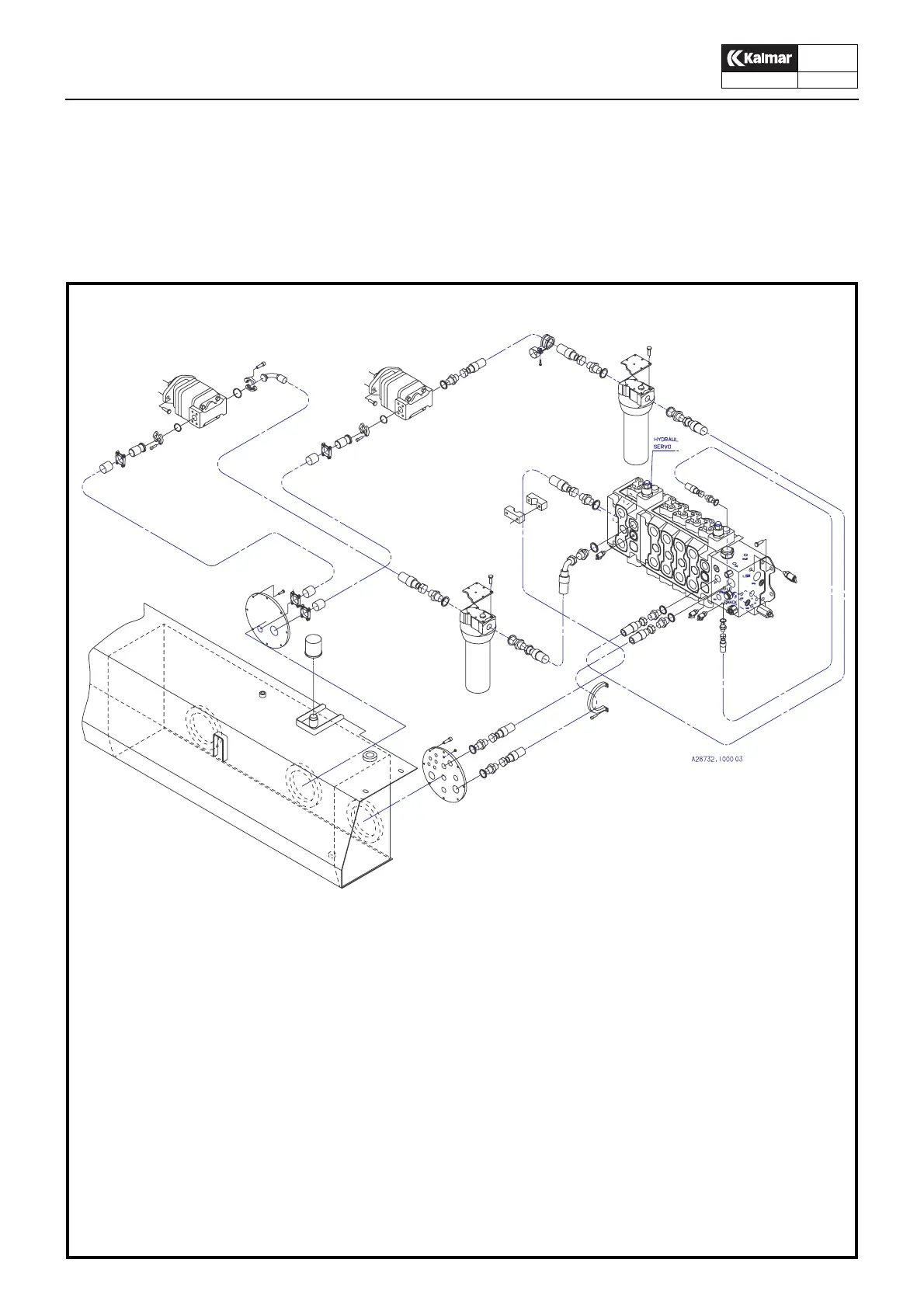
Hydraulic system, supply
The numbers correspond to the hydraulic diagram
20a. Hydraulic pump
20b. Hydraulic pump
23. High pressure filter
31. Hydraulic tank
50. Breather filter
31
50
23
23
20b
20a