DCE80-100E
Technical Handbook
Main hydraulics
Description
5
P.Group 70
TDCE01
04GB
Standard hydralic system, hydraulic servo
In its standard version, the hydraulic system is equipped with a
hydraulic servo-operated main valve. A pressure reducing valve
in the valve block delivers 35 bar servo pressure for the control-
lever valves. The servo fluid is then supplied to the main valve for
setting the valve spools, at a rate that is proportional to the lever
movement.
Safety interlock, container handling
To prevent accidents when lifting containers, the servo circuit for
lift is supplied with a solenoid valve. This is activated from the in-
ductive sensors for twist-locks locked or unlocked on the attach-
ment. Should the twist-locks not be fully locked or unlocked, lifting
is prevented.
In the same way the servo circuit for twist-locks is supplied with
two solenoid valves, one for locking and one for unlocking twist-
locks.
The solenoid valves are fed with signals from the inductive sen-
sors for alignment on the attachment. If full alignment is not
achieved, the locking and unlocking of twist-locks is prevented.
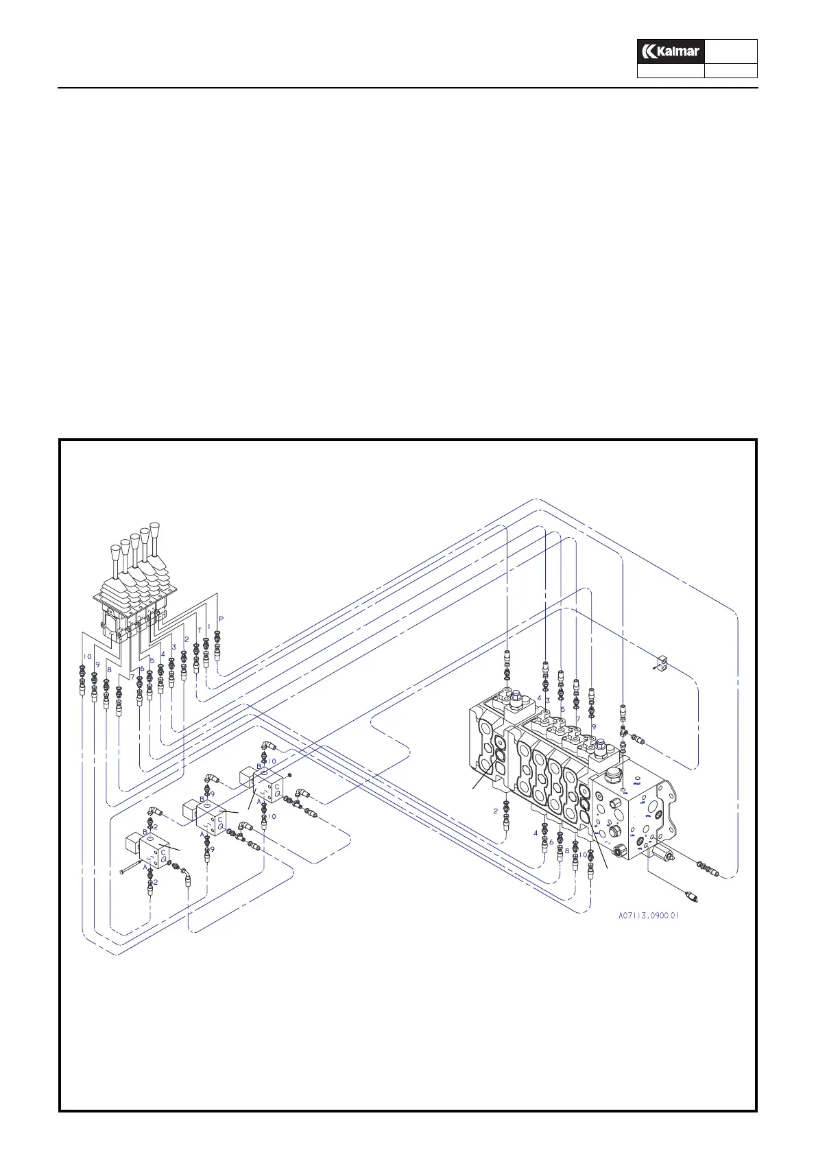
45
46
43
16
44
The numbers correspond to the hydraulic diagram
16. Control valve LIFT
43. Control levers
44. Control valve TWIST-LOCKS
45. Solenoid valve, brakes the servo circuit for TWIST-LOCKS
46. Solenoid valve, bryter the servo circuit for LIFT
Standard hydraulic system, hydraulic servo