DCE80-100E
Technical Handbook
Hydraulpumpar
Description
27
P.Group 70
TDCE01
04GB
Hydraulpumpar
Pump 18 +19 is a kombination pump where the inner section is a
variable piston pump 18 of constant pressure type and the outer
section is a fixed vane pump19.
Pump 20 a+b is a double fixed vane pump.
Variable axialkolvpump, see illustration next page
Pumps 18 that feeds the side-lift attachment is a variable axial
piston pump with five pistons placed in a cylinder rotor. The
stroke length of the pistons is determined by the position of an an-
gled pressure plate. The pistons are secured in slip-shoes that
rotate against the pressure plate. The stroke volume area and the
area within the pistons are filled with hydraulic fluid during the
suction phase. During the pressure phase, the hydraulic fluid is
fed into the pressure lines via a valve plate. A hole in the head of
each of the pistons allows hydraulic fluid to be forced out and
gives a balanced counter pressure from the pressure plate as
well as a film of fluid that lubricates the surfaces and inhibits wear.
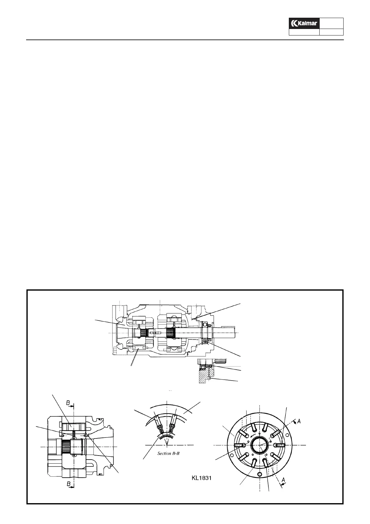
Fixed vanepump, see illustrations below and next page
These pumps consist of a pump casing and a pump unit, and are
of simple design. A rotor in the pump unit comprises a number of
vanes fitted in radial slots. The rotor is driven by a shaft and ro-
tates in a cam ring. The rotor vanes follow the profile of the cam
ring, and each vane performs two cycles – each comprising one
suction stroke and one delivery stroke – per revolution. The fluid
flows radially through the pump unit.
The vanes are forced outwards towards the cam ring by centrifu-
gal force and by thrust pins which are subjected to the same pres-
sure as the pump delivery pressure. This ensures that the vanes
will alwqys be in contact with the cam profile. An fluid film pre-
vents the vanes from coming into metallic contact with the cam
profile. In the same way, an fluid film prevents metallic contact
with the side plates.
Since the vanes, ports and pressures are balanced diametrically,
the net load on the rotor is a pure torque caused by the pumping
action. Sturdy shaft bearings carry the forces caused by the
pump drive.
4
1
2
3
7
8
13
15
16
14
14
9
10
11
12
Fast vingpump, dubbel
1. Replaceable cartridge assembly, includes cam
ring, rotor, vanes, pins and sideplates
2. Front and rear sideplates
3. Ball bearing
4. Front sideplate, is fixed axially by discharge
pressure to reduce internal leakage
5. –
6. –
7. Vane, is urged outward at suction ramp by pin
force and centrifugal force
8. Cam ring
9. Suction ramp where unloaded ramp moves out
10. Pressure ramp with working vanes which press
likquid towards the discharge port
11. Working vane on inor arc seals discharge pres-
sure from the suction port
12. Discharge ramp where unloaded vane
moves in
13. Pin cavity is at a steady pressure slightly higher
than at discharge port
14. Lub side holes, lubricate the sideplate surfaces
15. Pressure pins, force the vanes outward
16. Vanes