DCE80-100E
Technical Handbook
Hydraulpumpar
Description
28
P.Group 70
TDCE01
04GB
1
2
4
20
19
18
3
17
7
9
14
14
10
11
12
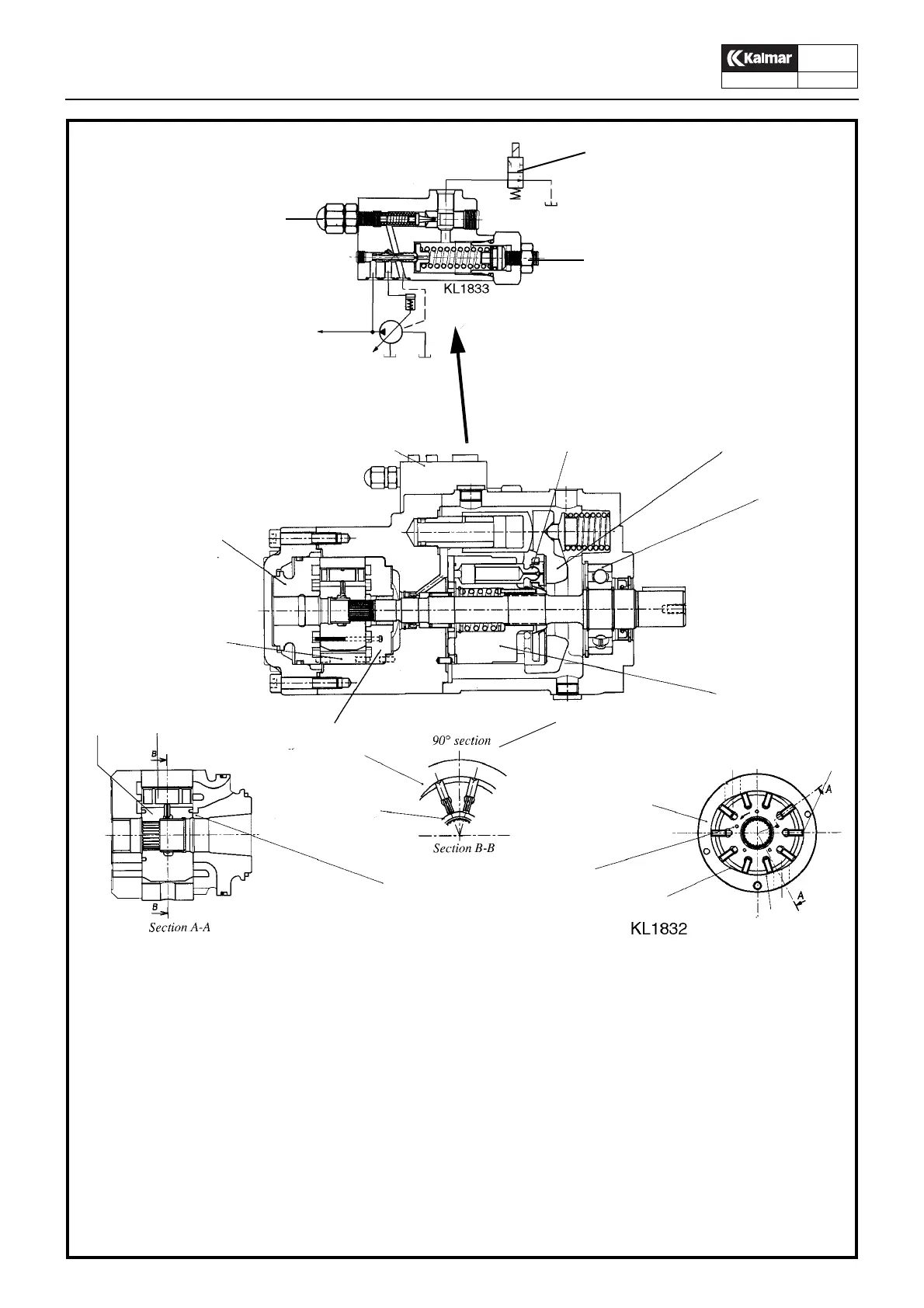
Fixed vane pump
1. Replaceable cartridge assembly, includes cam ring,
rotor, vanes, pins and sideplates
2. Front and rear sideplates
3. Ball bearing
4. Front sideplate, is fixed axially by discharge pressure
to reduce internal leakage
5. –
6. –
7. Vane, is urged outward at suction ramp by pin force
and centrifugal force
8. Cam ring
9. Suction ramp where unloaded ramp moves out
10. Pressure ramp with working vanes which press likquid
towards the discharge port
11. Working vane on inor arc seals discharge pressure
from the suction port
12. Discharge ramp where unloaded vane
moves in
13. Pin cavity is at a steady pressure slightly higher than
at discharge port
14. Lub side holes, lubricate the sideplate surfaces
15. Pressure pins, force the vanes outward
16. Vanes
Variable axial piston pump
17. Cylinderrotor
18. Ställskiva
19. Pumpkolv
20. Regulator
21. Justerskruv, stand-by tryck, 18 bar
22. Avlastningsventil
23. Justerskruv, pumptryck
21
22
23
8
13
15 16
Combination pump, variable piston pump and fixed vane pump