Features and Functions 3
Keysight 33210A User’s Guide 129
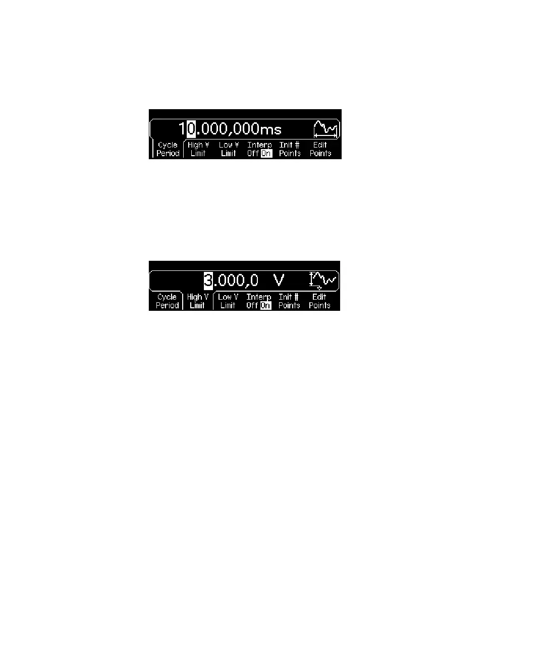
For this example, set the period of the waveform to 10 ms.
4 Set the waveform voltage limits.
Press the High V Limit and Low V Limit softkeys to set the upper and lower
voltage levels that can be reached while editing the waveform. The upper limit
must be greater than the lower limit. By default, Point #1 is set equal to the
upper limit and Point #2 is set equal to the lower limit.
For this example, set the upper limit to 3.0 V and the lower limit to 0 V.
5 Select the interpolation method.
Press the Interp softkey to enable or disable linear interpolation between
waveform points (this feature is available from the front panel only). With
interpolation enabled (default), the waveform editor makes a straight-line
connection between points. With interpolation disabled, the waveform editor
maintains a constant voltage level between points and creates a “step-like”
waveform.
For this example, turn on linear interpolation.
6 Set the initial number of waveform points.
The waveform editor initially builds a waveform with two points and
automatically connects the last point of the waveform to the voltage level of
the first point to create a continuous waveform. Press the Init # Points softkey
to specify the initial number of waveform points (you can add or remove points
later if necessary).
For this example, set the initial number of points to “4”.