154 Keysight Technologies N9040B UXA Signal Analyzer Service Guide
RF Section Troubleshooting (RF/Microwave Analyzers)
Troubleshooting
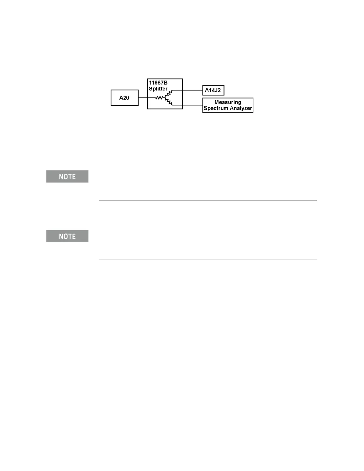
Figure 4-6 Measuring Setup
The signal should be 5172.5 MHz at +7 dBm ± 3 dB because of the 6 dB loss
through the 11667B splitter.
A13 Front End Assembly Verification
Many portions of the Front End Assembly have been verified earlier in the Low
Band troubleshooting process outlined above.
The input signal level was measured on W8 as part of the A11 Low Band
Switch verification.
The output signal level was measured at W16 during the quick check to verify
the Low Band Signal Path.
The Second LO input was tested during the Second LO Verification.
The LO input at W21, and the LO outputs were tested when performing the
First LO Verification.
Electronic Attenuator Test (Option EA3)
The electronic attenuator is aligned as part of the System Gain internal
alignment process. See the description of the initial alignments and the
location of the alignment history file in the Boot Up and Initialization
Troubleshooting chapter. Viewing the Alignment History file will tell you if
other alignment tests failed, and reveal which electronic attenuator steps
failed.
The output power from A20 is 5172.5 MHz at +13 dBm.
The A13 Front End assembly is shown as A13A1 and A13A2 for troubleshooting clarification.
However, A13A1 and A13A2 are not separately replaceable. The entire A13 assembly must be
replaced.

 Loading...


