Keysight Technologies N9040B UXA Signal Analyzer Service Guide 419
Assembly Replacement Procedures
Card Cage Boards
A14 L.O. Synthesizer
Removal
1. Refer to Figure 15-62. Locate the A14 L.O. Synthesizer assembly (4).
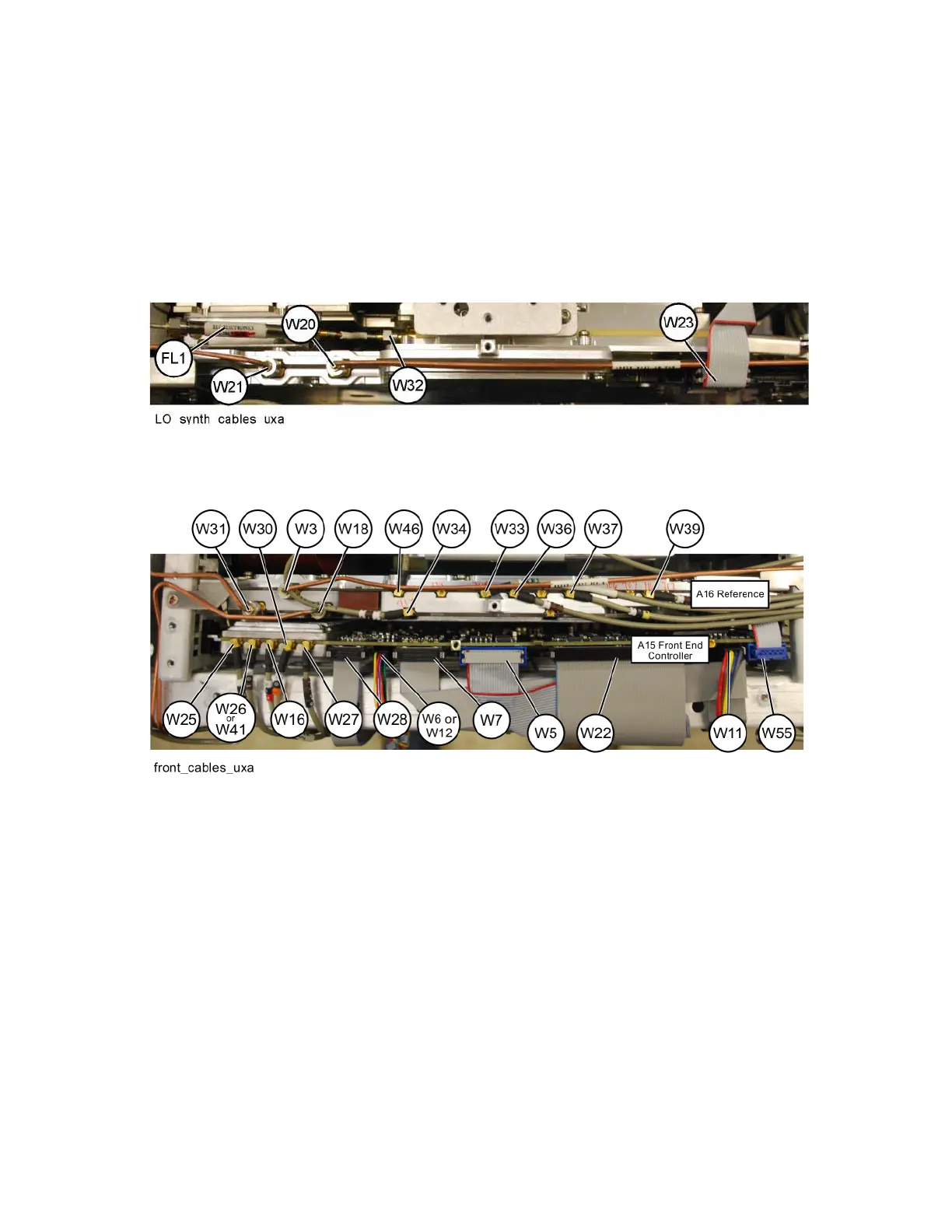
2. Refer to Figure 15-69. Remove cables W20, W21, W23, and W32.
Figure 15-69 L.O. Synthesizer Cables
3. Refer to Figure 15-70. Remove cable W31 from the Reference board.
Figure 15-70 Reference Board W31 Cable
4. Refer to Figure 15-66. Remove the two screws (4) (0515-1946) that
attach the L.O. Synthesizer assembly to the chassis. Use the ejector on the
L.O. Synthesizer assembly to unplug from the motherboard and lift out of
the chassis.
Replacement
1. Reinstall the L.O. Synthesizer assembly into the correct slot and use the
ejector to secure and to mate with the motherboard.
2. Refer to Figure 15-66. Replace the two screws (4) (0515-1946). Torque to
9 inch-pounds.
3. Refer to Figure 15-69. Reinstall cables W20, W21, W23, and W32. Torque
the semi-rigid cables to 10 inch-pounds.
4. Refer to Figure 15-70. Reinstall cable W31. Torque to 10 inch-pounds.

 Loading...


