Keysight Technologies N9040B UXA Signal Analyzer Service Guide 449
Assembly Replacement Procedures
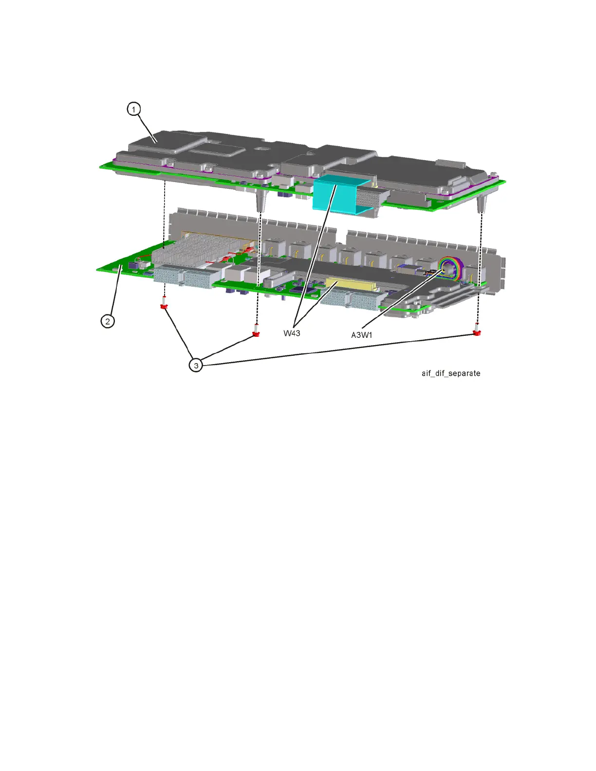
A2 AIF/A3 DIF
Figure 15-97 AIF/DIF Separation
1. To pair the AIF and DIF together again, set the DIF in position over the AIF.
Reinstall the three screws (0515-0372) removed before. Torque to
9 inch-pounds, starting with the middle screw.
2. Reconnect the ribbon cable W43.
Replacement
1. Slide the AIF/DIF assembly partially into the slot at the rear of the
instrument.
2. Refer to Figure 15-96. Replace cables W25, W36, and W42 to the AIF
assembly.
3. Push on the AIF/DIF assembly to mate the connectors to the motherboard
assembly.
4. Refer to Figure 15-95. Replace cables W39, W40, W42, and W47 to the
bottom of the DIF assembly.
5. Replace the rear panel. Refer to the “Rear Panel” replacement procedure.
6. Replace the instrument outer case. Refer to the “Instrument Outer Case”
replace procedure.

 Loading...


