Keysight Technologies N9040B UXA Signal Analyzer Service Guide 443
Assembly Replacement Procedures
A4 CPU/A5 Solid State Drive
A4 CPU/A5 Solid State Drive
Removal
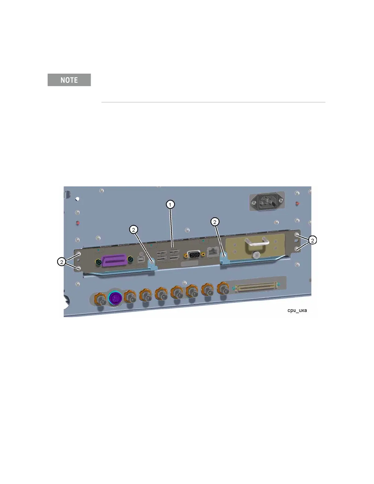
1. Refer to Figure 15-91. Remove the six screws (2) (0515-0372) that secure
the A4 CPU assembly (1) to the chassis. Use the ejectors to disconnect
the CPU from the rear motherboard and remove it from the chassis.
Figure 15-91 CPU Removal
Replacement
1. Refer to Figure 15-91. Slide the CPU assembly into the slot and use the
ejectors to mate the CPU with the rear motherboard. Replace the six
screws (2) (0515-0372). Torque to 9 inch-pounds.
To remove the SSD or the memory card, it is not necessary to remove the CPU assembly from
the chassis. See the “Replacement of A5 SSD or A4A1CPU Memory Card” procedure on
page 444.
 Loading...


