Keysight Technologies N9040B UXA Signal Analyzer Service Guide 465
Assembly Replacement Procedures
Motherboards
4. Replace AIF/DIF assembly. Refer to the “A2 AIF/A3 DIF” replacement
procedure.
5. Replace the power supply. Refer to the “A6 Power Supply” replacement
procedure.
6. Replace the CPU assembly. Refer to the “A4 CPU/A5 Solid State Drive”
replacement procedure.
7. Replace the wideband digital I.F. assemblies if present. Refer to the “A22
& A23 Wideband Digital I.F. Boards” replacement procedure.
8. Replace the front motherboard. Refer to the “Front Motherboard (A8 Front
Motherboard)” replacement procedure.
Bottom Motherboard (A24 Motherboard Interconnect)
Removal
1. Remove the front motherboard. Refer to the “Front Motherboard (A8 Front
Motherboard)” removal procedure.
2. Remove the rear motherboard. Refer to the “Rear Motherboard (A7 Rear
Motherboard)” removal procedure.
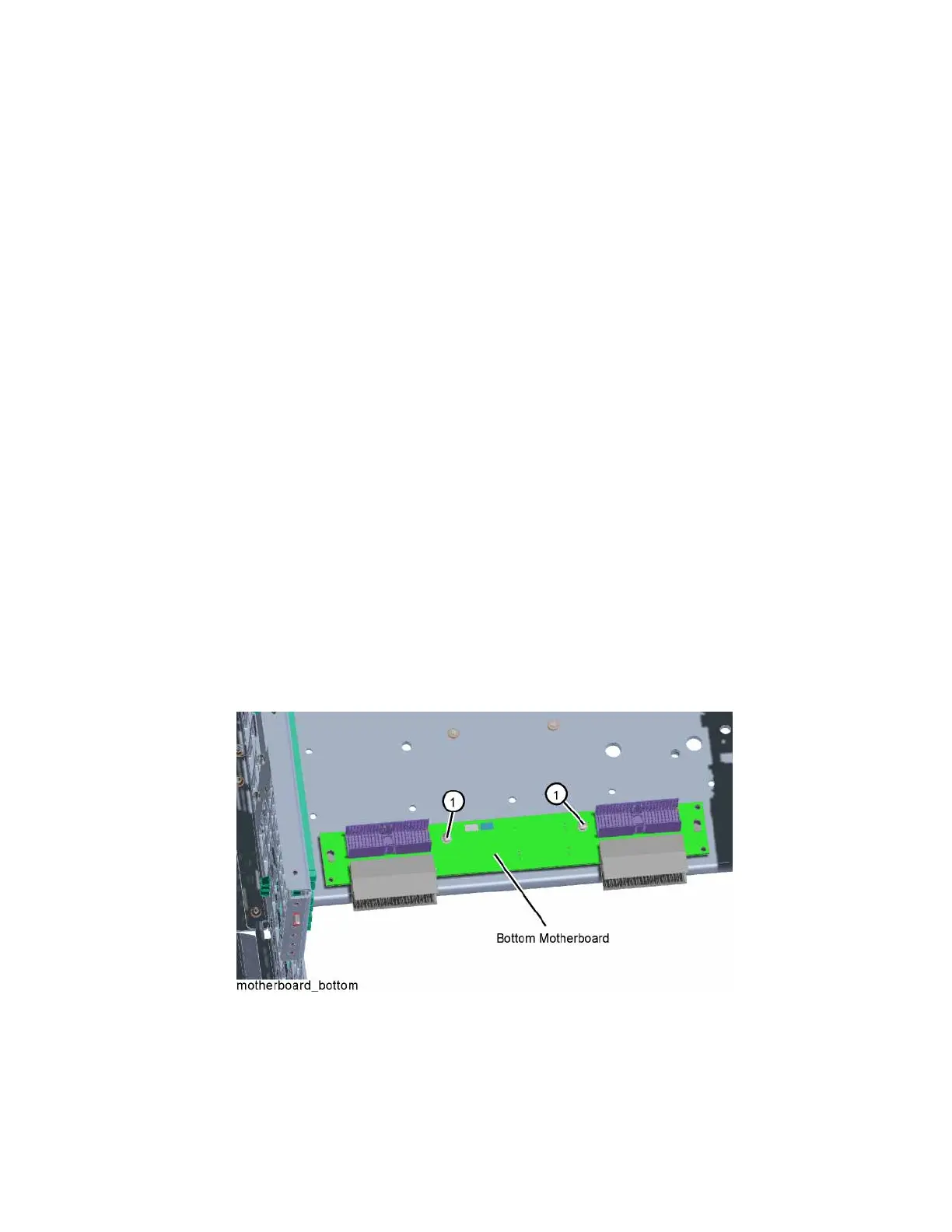
3. Refer to Figure 15-112. Remove the two screws (1) (0515-0372) that
attach the bottom motherboard to the chassis. Push the bottom
motherboard forward to disengage from the locking pins on the chassis.
Figure 15-112 Bottom Motherboard Removal

 Loading...


