Keysight Technologies N9040B UXA Signal Analyzer Service Guide 431
Assembly Replacement Procedures
A27 H1G Assembly (Option H1G)
Replacement process when the H1G assembly is the later version
Removal
1. Remove the instrument outer case. Refer to the “Instrument Outer Case”
removal procedure.
2. Remove the top brace. Perform step 3 in the “Top Brace and Card Cage
Brace” removal procedure. Save the screws for reuse.
3. Remove the screws from the rear panel and carefully pull away from the
instrument. Avoid damaging the cables attached.
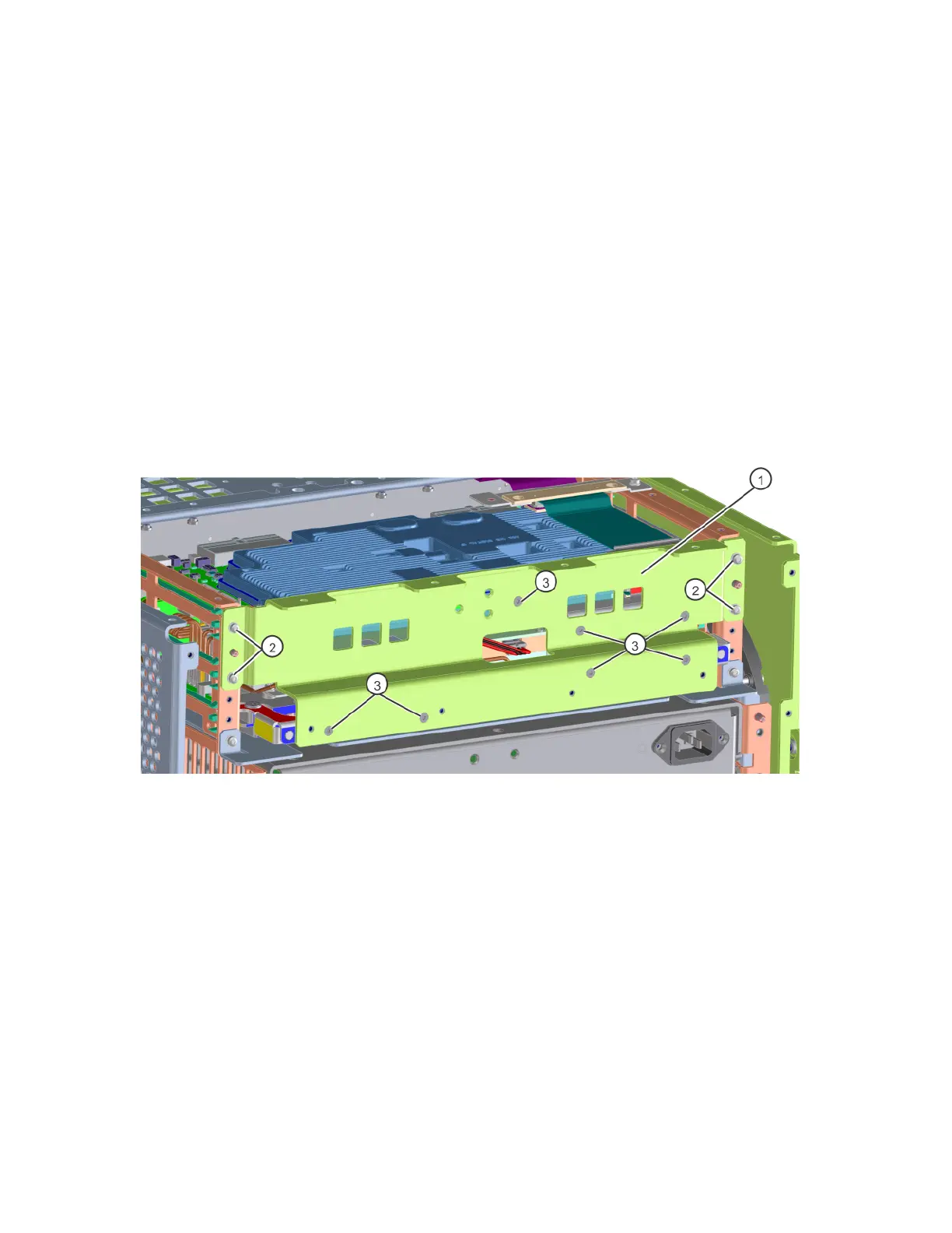
4. Refer to Figure 15-79. Remove the rear brace (1) by removing the four
screws (2) (0515-0372) and the seven screws (3) (0515-1946). Save the
screws for reuse.
Figure 15-79 Rear Brace Removal
5. Locate the H1G assembly and use the board extractor handles to loosen
the board slightly and allow access to the coax cables attached to the
board.
6. Remove the snap-in cables from the board assembly. Remove the blue
cable from the H1G assembly J12 using a 5/16-inch wrench. See Figure
15-80.

 Loading...


