358 Keysight Technologies N9040B UXA Signal Analyzer Service Guide
Assembly Replacement Procedures
RF Area - Options 508, 513, 526
RF Area - Options 508, 513, 526
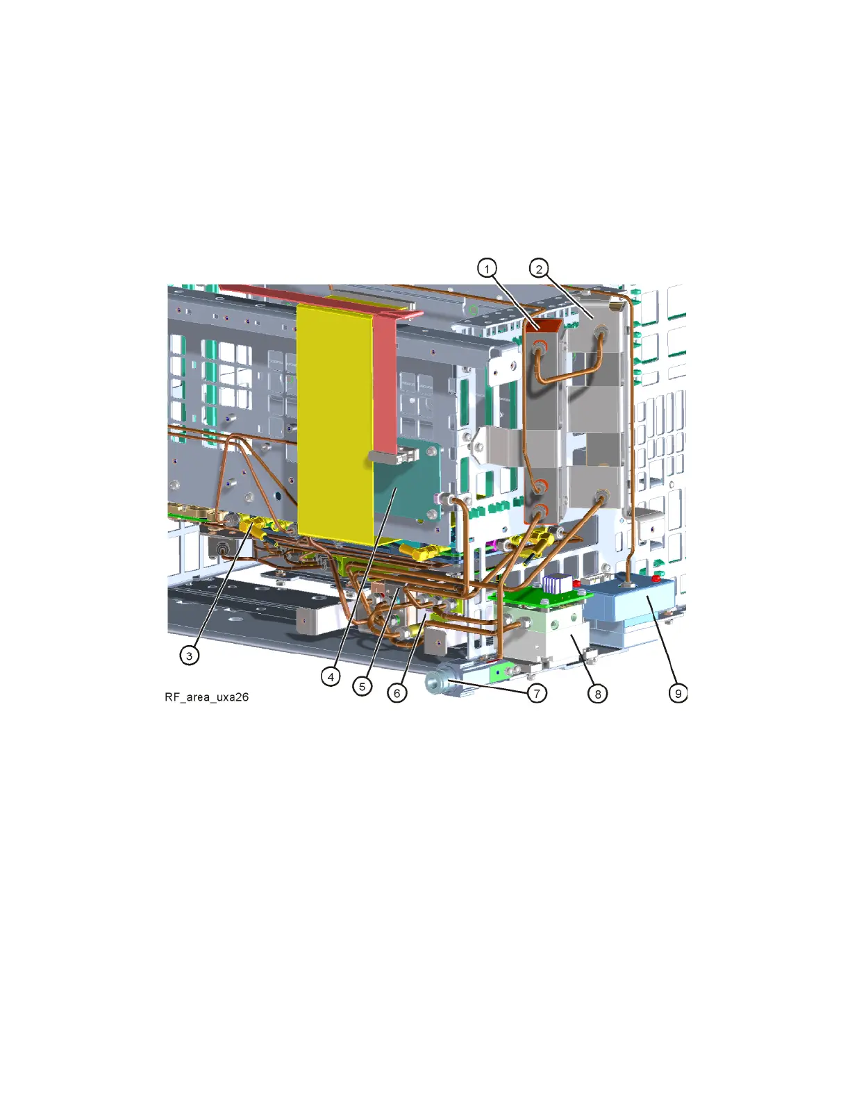
Refer to Figure 15-6. The RF area consists of A9 RF attenuator A (1), A10 RF
attenuator B (2), A13 front end assembly (3), A11 low band switch assembly
(4), transfer switch SW3 (5), coax switches SW1 and SW2 (6), RF input
connector (7), A12 YTF Preselector (8 ), and A20 YTO (9).
Figure 15-6 RF Area Components - Options 508, 513, 526
To gain access to any of the RF section parts for removal,
follow these steps:
1. Remove the instrument outer case. Refer to the “Instrument Outer Case”
removal procedure.
2. Remove the front panel. Refer to the Front Frame Assembly removal
procedure.

 Loading...


