406 Keysight Technologies N9040B UXA Signal Analyzer Service Guide
Assembly Replacement Procedures
RF Area - Options 544, 550
A13 RF Front End Assembly
Removal
1. Perform step 1 through step 3 in the “Transfer Switches” removal
procedure on page 399 to remove the bracket and switch assembly.
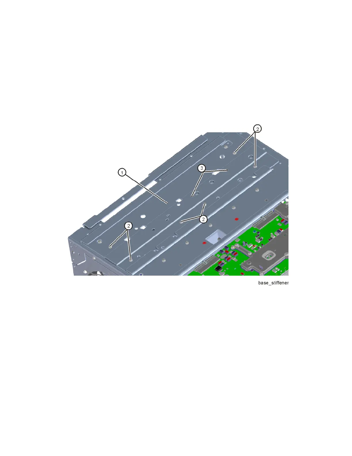
2. Refer to Figure 15-54. Remove the chassis base stiffener (1) by removing
the six screws (2) (0515-0372) and the two screws (3) (0515-1946).
Figure 15-54 Chassis Base Stiffener Removal

 Loading...


