EasyManuals Logo

Keysight N9040B Option 508 User Manual

Keysight N9040B Option 508
542 pages
To Next Page IconTo Next Page
To Previous Page IconTo Previous Page
Page #467 background imageLoading...
Page #467 background image
Keysight Technologies N9040B UXA Signal Analyzer Service Guide 467
Assembly Replacement Procedures
Input Connector
Input Connector
Removal
1. Remove the instrument outer case. Refer to the “Instrument Outer Case”
removal procedure.
2. Remove the front frame. Refer to the “Front Frame Assembly” removal
procedure.
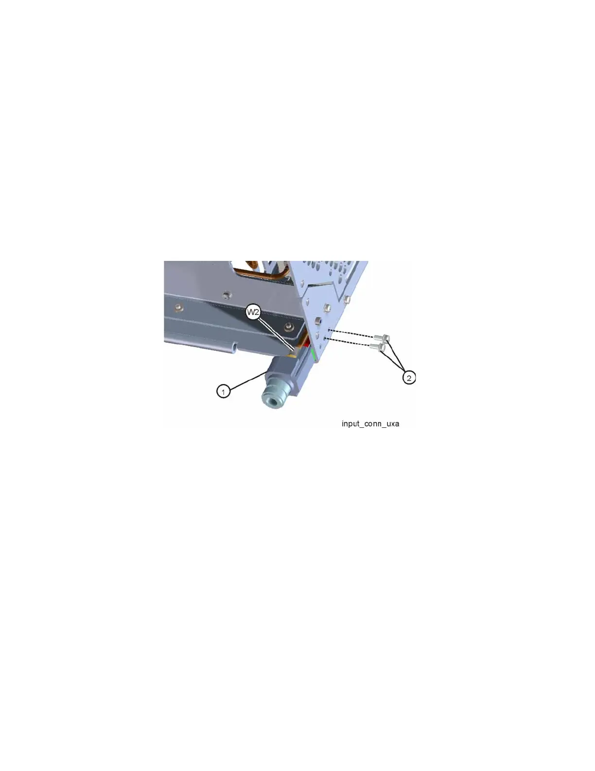
3. Refer to Figure 15-113. Disconnect the W2 semi-rigid cable from the input
connector (1).
Figure 15-113 Input Connector Removal
4. Remove the two screws (2) (0515-0372) that attach the input connector
to the chassis.

Table of Contents

Questions and Answers:

Question and Answer IconNeed help?

Do you have a question about the Keysight N9040B Option 508 and is the answer not in the manual?

Keysight N9040B Option 508 Specifications

General IconGeneral
BrandKeysight
ModelN9040B Option 508
CategoryMeasuring Instruments
LanguageEnglish

Related product manuals