172 Keysight Technologies N9040B UXA Signal Analyzer Service Guide
Front End Control Troubleshooting
A15 Front End Control Assembly Troubleshooting
Verifying Input Attenuator A, Input Attenuator B, Low Band Switch
Logic and Power Supplies
1. Turn off the instrument.
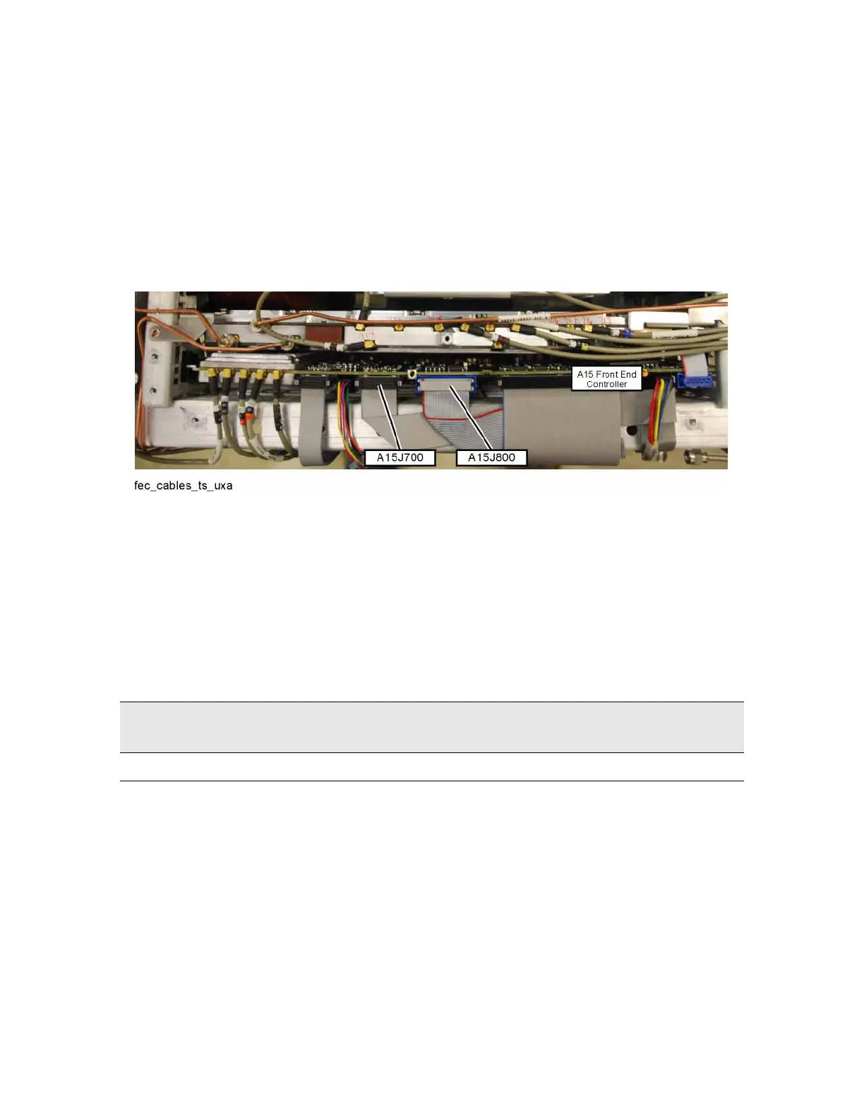
2. Disconnect ribbon cables from A15J700 and A15J800 as shown Figure
5-2.
Figure 5-2 Ribbon Cables at A15J700 and A15J800
3. Connect the E4410-60115 RF Front End Troubleshooting board to the A15
Front End Control board using the E4410-60157 attenuator control cable.
When connecting the attenuator control cable, E4410-60157, note that
one end has two 10-pin connectors with one connector extending beyond
the other. The shorter connector is marked with a red stripe. Connect the
end with the 20-pin connector to A15J800. Connect the two 10-pin
connectors to either J3 or J4 of the RF Front End Troubleshooting board
based upon the UXA’s frequency range as described below:
4. If the UXA has frequency range option 508, 513, or 526, also connect the
Low Band Switch Control Cable, E4410-60160 between A15J700 and J2
of the RF Front End Troubleshooting board.
Table 5-3 UXA Frequency Range
Frequency
Range Option
Shorter 10-pin connector
(marked with red stripe)
Longer 10-pin connector
508, 513, or 526 J3 J4

 Loading...


