360 Keysight Technologies N9040B UXA Signal Analyzer Service Guide
Assembly Replacement Procedures
RF Area - Options 508, 513, 526
4. Serial Number Prefix ≥ 5605:
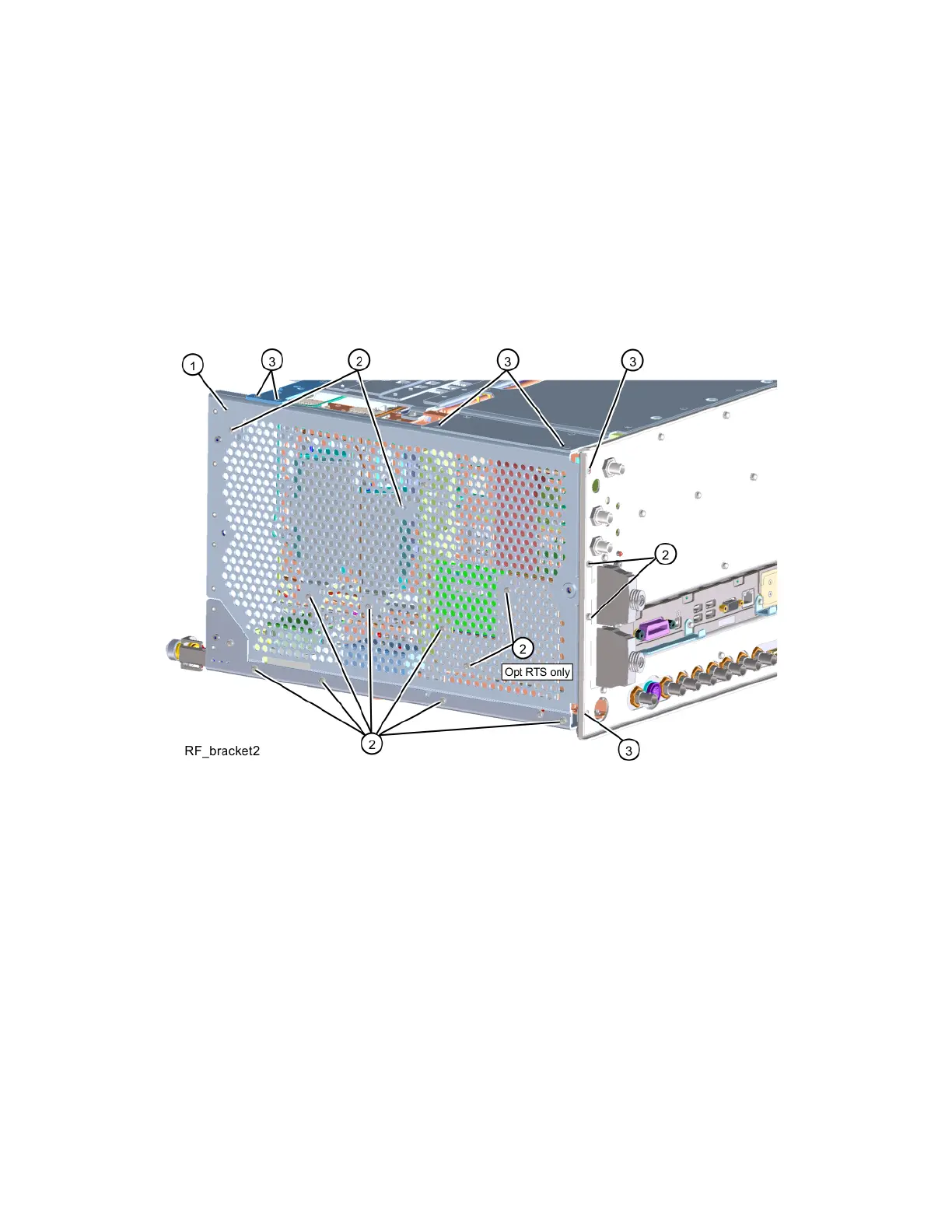
— To access the attenuators, the YTF Preselector, or the YTO, it is
necessary to also remove the RF bracket. Refer to Figure 15-8.
Remove the RF bracket (1) by removing the eleven (or thirteen with
Option RTS) screws (2 ) (0515-0372), and the six screws (3)
(0515-1946), using the T-10 driver.
Figure 15-8 RF Bracket Removal,
Serial Number ≥ Prefix 5605 Options 508, 513, 526
After the part has been replaced, follow these steps:
1. Refer to Figure 15-7 or Figure 15-8. Position the RF bracket onto the
chassis and replace the screws (2) (0515-0372), and the screws (3)
(0515-1946), using the T-10 driver. Torque to 9 inch-pounds.
2. Replace the front panel. Refer to the Front Frame Assembly replacement
procedure.
3. Replace the instrument outer case. Refer to the “Instrument Outer Case”
replacement procedure.

 Loading...


