Installation
06-237619-001 4-3 April 2020
4-4.1 System Overview
The cylinders, stored in the bank, are individually connected to the manifold assembly. The
connection is made with high-pressure hoses and a manifold check valve, one for each
cylinder. The manifold check valves allow for removal of one or more cylinders from the
manifold without having a significant loss of Agent should the remaining cylinders be
discharged.
The system can be released electronically by a control panel sending a signal to the release
unit.
Note: Release unit solenoids must be continuously powered during system discharge.
The system can be released manually by removing the locking pin and turning the wheel of the
master cylinder manual release unit in the direction of the arrow (clockwise).
Each cylinders can be equipped with a pressure gauge for low pressure monitoring. The
“master” cylinder will include a solenoid valve release unit. The pressure from the “master”
cylinder is channeled to valves on the slave cylinders, releasing their content. During a
discharge, the cylinders in the cylinder bank will be released almost simultaneously.
Note: Kidde recommends that the release unit be installed on the left most cylinder if possible.
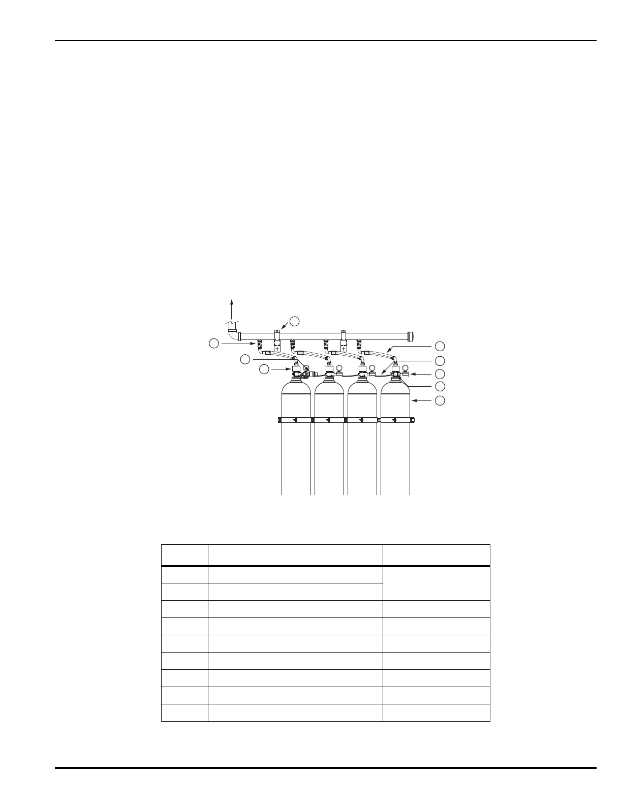
Figure 4-1. Single Area Cylinder Bank Arrangement
Table 4-1. Single Area Cylinder Bank Arrangement Components
Item Description Part Number
1 Agent Cylinder
38-42XXX1-XXX
2Valve
3 Release Unit 38-400001-00X
4 Slave Cylinder Gauge Assembly 38-400005-00X
5 Actuation Hose 38-4011X0-X00
6 Pilot Line Bleed Valve (on back side) 38-400007-001
7 Discharge Hose 38-400330-X10
8 3/4” BSP Manifold Check Valve 38-400002-002
9 Manifold Bracket Clamp 01-8143-0000
To Distribution
Pipe Work
1
2
4
5
7
6
8
9
3