System Design
April 2020 3-10 06-237619-001
3-8.2 Hold Time
Design concentration shall not only be achieved within the prescribed discharge time, but also
that the extinguishing concentration shall be maintained for the specified period of time to
allow effective emergency action by trained personnel. This is equally important in all classes
of fires (A, B, & C) since a persistent ignition source (e.g. an arc, heat source, oxyacetylene
torch, or deep-seated fire) can lead to resurgence of the initial event once the Agent has
dissipated.
The hold time should not be less than 10 minutes or as agreed with authorities having
jurisdiction or comply with ISO 14520/BS EN 15004 latest or NFPA 2001, 2015 edition
requirements.
Note: The hold time for locations remote from a fire station may require a longer “Hold” time.
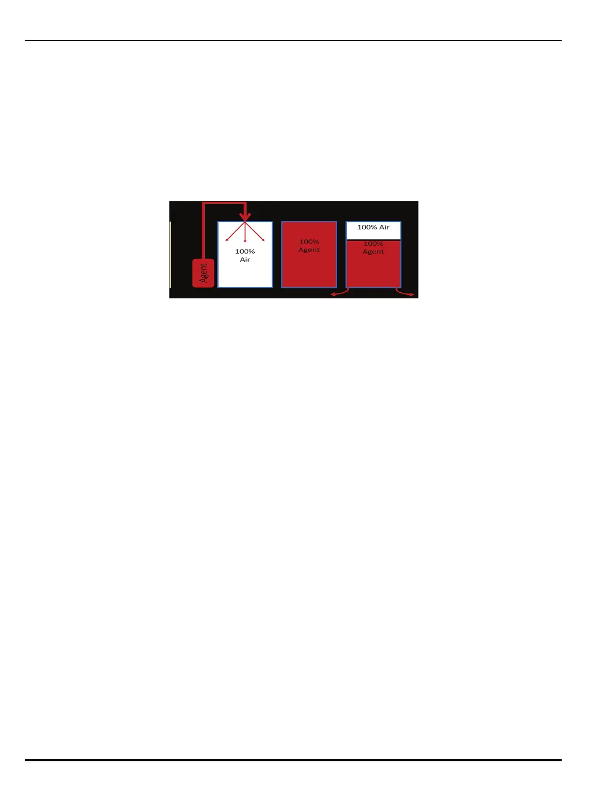
Figure 3-1. Hold Time Model
Note: Figure 3-1 is based on the NFPA model for descending interface where 100% of the ini-
tial concentration leaks out the bottom of the enclosure which replaces the lost volume
with 100% above the interface.
3-8.3 Temperature Considerations
During discharge the temperature within the protected enclosure will drop approximately
9-18 °F (5 – 10 °C). The temperature will rise again after approx. 2 – 3 min. The Kidde IGS
system is designed and tested to operate with a temperature range of
-4 to 130 °F (-20 to 54 °C).
3-8.4 Flow Calculation
In order to design an Agent fixed fire-extinguishing system a listed flow calculation program
shall be used. Refer to the Kidde IGS Flow Calculation manual (P/N 06-237621-001) for details
of the Kidde IGS flow-calculation software.
3-8.4.1 Required Input Information
The flow calculation program requires the following input:
• Cylinder storage pressure in absolute pressure (at room temperature).
• Room temperature (start of pipe).
• Enclosure volumes including elevated floors & suspended ceilings.
• Total quantity of Extinguishant allowed
• Cylinder size (80 liter)
• Number of cylinders.
• Discharge time required (60 or 120 seconds).
• Number of nozzles selected per void (even quantity of gas discharged per nozzle per void).
• Piping data, estimated pipe dimensions, pipe quality selected.
Note: Due consideration to flow/length/pressure drop in pipe sections to be taken when esti-
mating pipe dimensions.
• Maximum pressure that building parts can withstand (normally 5 mbar maximum).