Installation
April 2020 4-46 06-237619-001
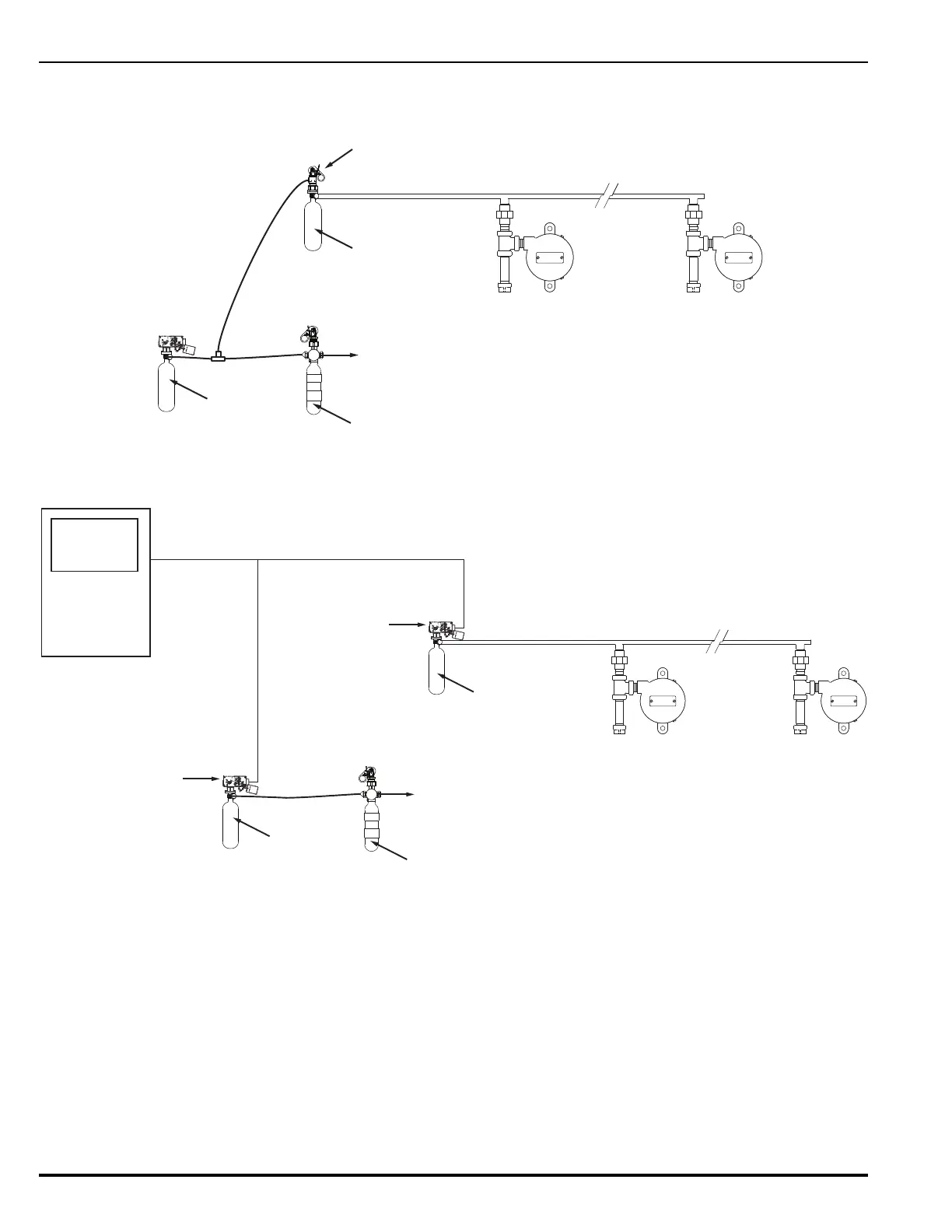
4-17.5.1 Sample Siren Setups
The following show two possible examples for operating the siren.
Figure 4-36. Siren with Pneumatic Activation
Figure 4-37. Siren with Electric Control Head Activation
4-18 INSTALLATION OF PRESSURE TRIP, P/N 81-874290-000
Install the pressure trip on the discharge manifold or piping in the horizontal position as shown
on the system drawings. Connect the trip to the piping with 1/2-inch Schedule 40 pipe. The
minimum operating pressure required is 75 psig (5.17 bar gauge). The maximum allowable
load to be attached to the retaining ring is 100 lb (45.3 kg).
4-19 INSTALLATION OF DISCHARGE INDICATOR, P/N 81-875553-000
The discharge indicator must be installed on the discharge manifold, either in a vertical or
horizontal position. The indicator has a 3/4-inch (19 mm) NPT male connection. Make certain
the indicator stem is in the normal position.
To Pressure Regulator
and Agent Cylinders
NOTE: Components not to scale
Dedicated N2
Siren Driver
Pressure and Lever
Operated Control Head
Discharge Delay
N2 Pilot
Cylinder
Note: Siren Driver size determines
maximum number of allowed sirens.
To Pressure Regulator
and Agent Cylinders
NOTE: Components not to scale
Dedicated N2
Siren Driver
Discharge Delay
N2 Pilot
Cylinder
Note: Siren Driver size determines
maximum number of allowed sirens.
Electric
Control Head
Electric
Control Head
Control Panel