Installation
06-237619-001 4-43 April 2020
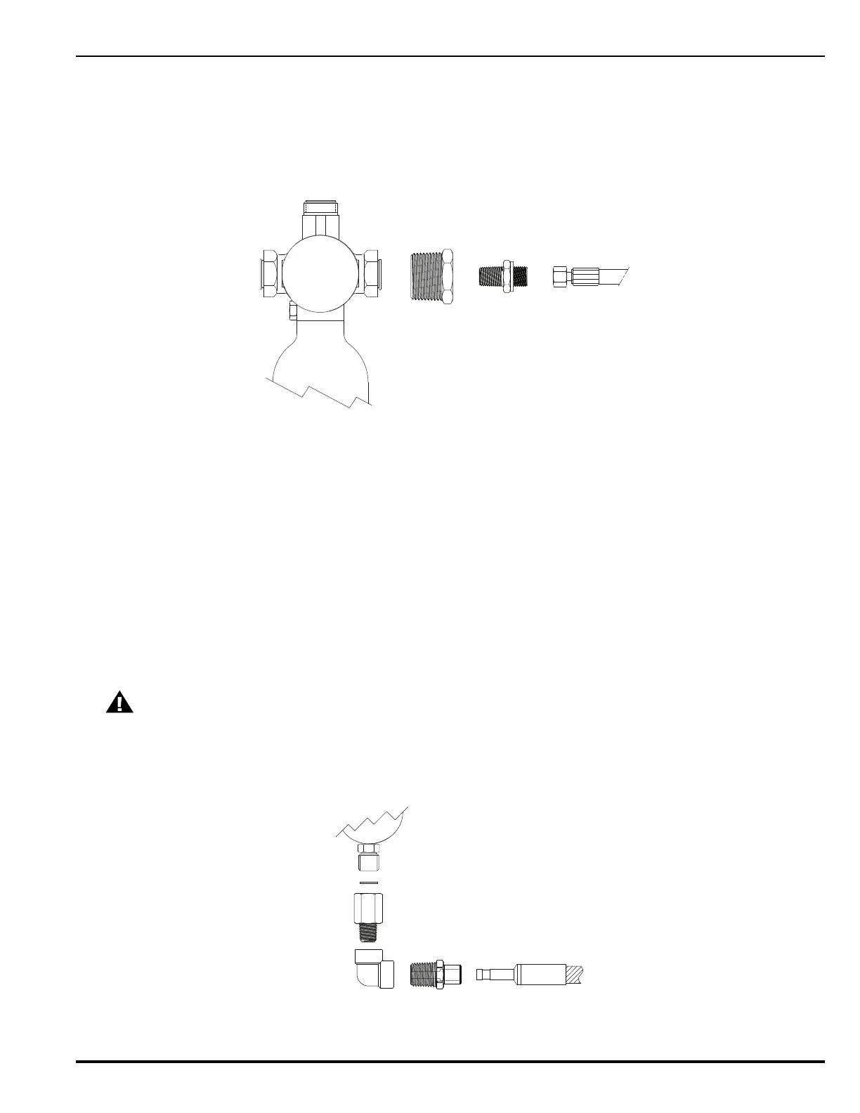
4-17.4.1 Connecting Discharge Delay to the Pressure Regulator and Cylinder Valve
Follow these steps when connecting the discharge delay to the pressure regulator and valve.
1. After installing the discharge delay, connect the 3/4” male x 1/4” NPT female bushing
adapter to the outlet on the discharge delay.
2. Screw the 1/4” BSPP male x NPT male straight adapter into the bushing adapter.
3. Connect the straight adapter to the back-plate manifold hose (P/N 01-6017-0000).
Figure 4-32. Discharge Delay Outlet Adapters and Hose
4. Mount the Pressure Regulator and connect the back-plate manifold hose to the inlet on the
pressure regulator.
5. Insert the copper washer into the 1/4” BSPP female end of the 1/4” BSPP female x NPT
male straight adapter.
6. Screw the 1/4” BSPP female end of the 1/4” BSPP female x NPT male straight adapter onto
the outlet of the pressure regulator.
7. Connect the 1/4” NPT female 90° elbow connector to the male end of the 1/4” BSPP female
x NPT male straight adapter.
8. Screw the threaded male end of the 1/4” NPT male x 6mm Tube OD adapter into the 90°
elbow connector.
9. Connect an actuation hose (P/N 38-401110-X00 or 38-401130-X00) into the tube end of
the 1/4” NPT male x 6mm Tube OD adapter. Make sure to push the actuation hose in fully.
10. Do not connect the actuation hose the cylinder valve at this time. That should be performed
during final commissioning.
Figure 4-33. Pressure Regulator Outlet Adapters and Hose
CAUTION
Ensure the actuation hose is fully inserted into the adapter. There should be a
gap of no more than 1/4” (6 mm) between the end of the festo connector and
the adapter quick connect.
3/4” Male x 1/4” Female
Bushing Adapter
1/4” BSPP Male x NPT Male
Straight Adapter
Back-Plate Manifold
Hose
Discharge Delay
Outlet
Copper Washer
1/4” BSPP Female x NPT Male
Straight Adapter
1/4” NPT Female
90° Elbow Connector
Actuation Hose
1/4” NPT Male
x 6mm Tube OD
Adapter
Pressure Regulator