Installation
06-237619-001 4-49 April 2020
4-22 LOCKOUT VALVES
Note: Lockout valves are required when the agent concentration is at or above the LOAEL
The lockout valve with limit switch must be installed in the discharge pipe network, down-
stream of all cylinders, check valves, and selector valves. All valves should be easily accessible.
Lockout valves can be installed in either the vertical or horizontal position using good pipe fit-
ting practices. Place two to three wraps of Teflon tape on male threads of pipe. A union is rec-
ommended after the valve to facilitate future service work. The valve should be locked in the
“open” position using a padlock. All valves must be electrically supervised.
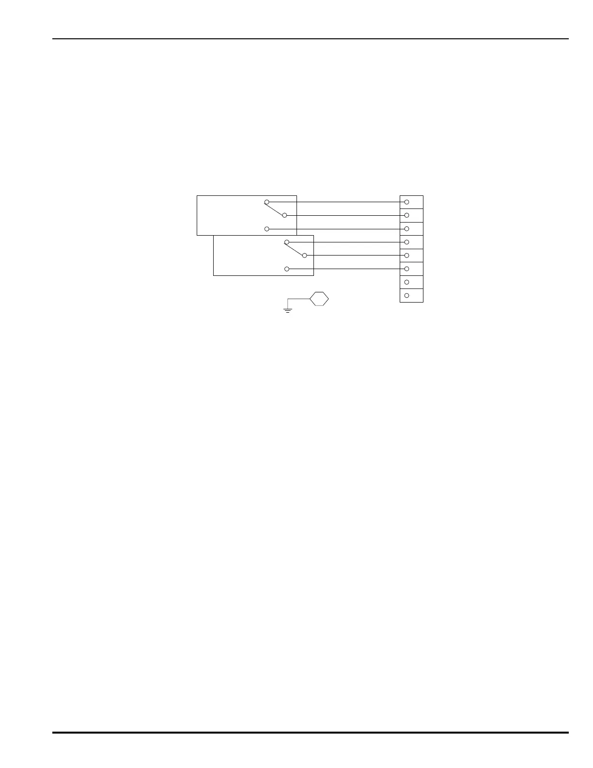
Figure 4-39 shows the lockout valve wiring diagram when the ball valve is in the fully open
position.
Figure 4-39. Wiring Diagram for Lockout Valve when Ball Valve is in Fully Open Position
1
2
3
4
5
6
7
8
Brown
Purple
Yellow
Orange
Blue
Red
GND
NC
C
NO
NC
C
NO
Switch
#1
Upper
Switch
#2
Upper