Installation
April 2020 4-4 06-237619-001
4-4.2 Selector Valve System
In selector valve systems, the Agent may be distributed to various hazards from a common
cylinder bank. Only one hazard can be protected at a time. Therefore, it is recommended that
a reserve bank of cylinders is maintained such that continuous fire suppression is available in
the event of a discharge. The number of cylinders released per hazard is controlled by using a
solenoid release unit for each “master” cylinder in the bank. By only energizing certain
“master” cylinders, the amount of agent released can be limited to the amount needed for the
given hazard.
A low-pressure back-plate manifold incorporating low-pressure 2 way solenoid valves controls
the pressure directed to the selector valves. Each solenoid valve controls a specific selector
valve, with each selector valve allowing access to one hazard.
Note: The solenoid on the back-plate manifold leading to the hazard being protected by the
discharge must be continuously powered during the system discharge.
The back-plate manifold receives propellant pressure from the discharge manifold. The
propellant pressure is reduced to 8 bar by a pressure-reducing valve.
The fire alarm and control panel will simultaneously energize the high-pressure release
solenoid valve on the master cylinders in the bank and the associated low-pressure solenoid
valve on the backplate manifold for the area where a fire is detected.
For safety reasons, selector valves are supplied as dual action. The selector valves shall be
closed in the normal standby position and only open during a discharge. The selector valve
needs to be closed manually after the discharge and before resetting the system with a new
set of cylinders. The selector valves are not self-resetting.
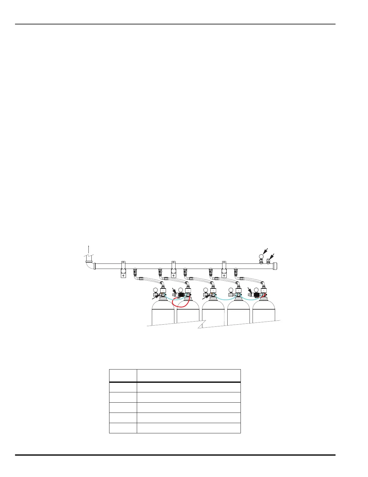
In Figure 4-2, there are two release units. The Hazard 1 release unit would fire 3 cylinders. The
Hazard 2 release unit would only fire 2 cylinders. If a third Hazard required all 5 cylinders, both
release units would need to activate.
Figure 4-2. Typical Pilot Line on Selector Valve System (Rear View)
Table 4-2. Components for Typical Pilot Line
Item Description
1 Hazard 1 Release Unit
2 Hazard 2 Release Unit
3 Pilot Line Bleed Valve
4 Manifold Safety Device
5 Manifold Pressure Gauge
To Distribution
Pipe Work