Installation
April 2020 4-12 06-237619-001
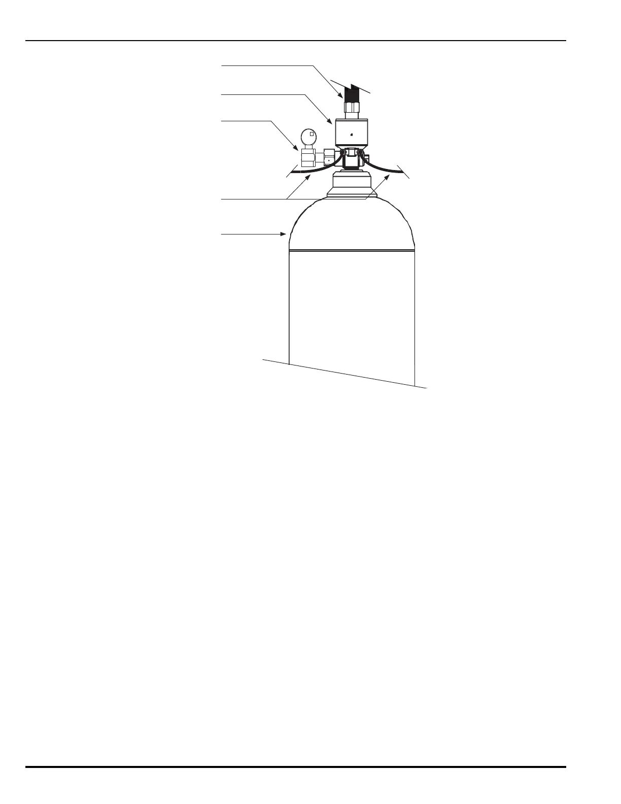
Figure 4-10. Typical Slave Cylinder/Valve Assembly (Rear View)
4-6 CYLINDER BANK ASSEMBLY
4-6.1 Securing Manifold
Before measuring the placement of the manifold brackets, check the cylinder height(s) to en-
sure accuracy to the design plan. Install manifold supports in such a way to allow for vertical
adjustment if necessary. Follow this procedure to secure the manifold:
1. Use 1/2” expansion bolts (or equivalent) with washer or similar to secure the channel
iron/Unistrut to a wall or solid structure. On steel structures, The channel iron/Unistrut
®
could be fixed by welding.
2. Tighten bolts in accordance with the manufacturer’s recommendation for the selected fixing
and the strength of the wall.
3. Ensure that the brackets are horizontal, level, and at the same height as indicated on the
cylinder bank assembly drawing.
4. Fix the manifold loosely to the channel iron/Unistrut by using the pipe clamps (pipe clamps
are not to be tightened at this stage, as adjustment of the manifold may be required when
cylinders are in place).
5. Install distribution pipe work, see Section 4-8.
Valve
Slave Cylinder
Gauge Assembly
Actuation Hose
Cylinder
Discharge Hose