Installation
06-237619-001 4-15 April 2020
4-6.6 Positioning Cylinders
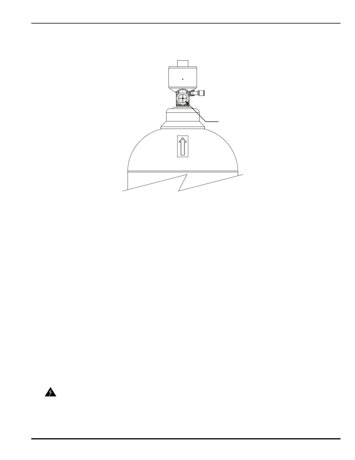
For ease of positioning the cylinder, the gauge port is marked by a label on the shoulder of the
cylinder.
Figure 4-12. Cylinder Valve Gauge Port
Follow this procedure to install the cylinders after they have been secured in their brackets:
1. Remove the transport cap from the cylinder. Store the cap in a convenient place for future
use.
2. Ensure that the gauge port is pointing to the right.
3. Remove the anti-recoil cap from the valve’s discharge outlet.
4. Leak test the outlet port of the cylinder valve by means of ammonium-free leak detection
liquid. If visible leakage occurs, replace the cylinder.
5. Connect the discharge hose to the discharge outlet on top of the cylinder valve. Do not
tighten the swivels on hose at this stage.
6. Leak test gauge port of the cylinder valve by means of ammonium free leak detection liquid
or spray, ensuring that there is no leakage.
7. Install the “quick connect” pilot hoses linking each cylinder. Use the longer hoses to link
rows to each other.
8. Install the Pilot Line Bleed Valve to the pilot line on the last cylinder.
9. Tighten the nuts on the clamping bolts, securing the cylinders. Use 1” & 3/4” or equivalent
fixed spanners and torque to 29.5-33.2 ft lb (40 – 45 N-m).
Note: Do not use the clamping bolt as a means of pressing the cylinder into the bracket.
10. Install a protecting nut on the free thread end, tightening slightly.
11. Tighten the pipe clamps for the distribution manifold. Use an 3/4” or equivalent fixed span-
ner, torque: 14.75-18.5 ft lb (20 – 25 N-m).
WARNING
Cylinders not connected to the manifold must have anti-recoil safety caps on
the discharge outlet.
GAUGE PORT
Gauge Port