Component Descriptions
April 2020 2-32 06-237619-001
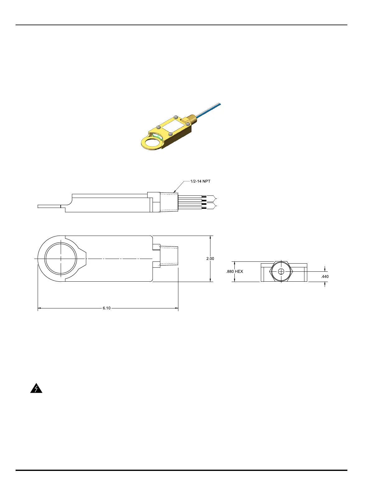
2-8.4.2 Control Head Monitor with Hazloc Assembly,
P/N 85-100000-100
The Control Head Monitor with Hazloc assembly provides supervision for control head place-
ment in normal and explosive environments in one easy to install component.
The following specifications apply to the Control Head Monitor:
• Rated Voltage: 42 VDC maximum
• Resistive Load: 0.5A maximum
Figure 2-39. Control Head Monitor with Hazloc Assembly
Figure 2-40. Control Head Monitor Dimensions
This component can be placed between the nitrogen pilot cylinder (P/N: 90-101040-000 or
WK-877940-000) and one of the following Electric or Electric/Cable operated control heads
(P/N: WK-890181-000, WK-897494-000, 82-486500-010, and 81-895630-000).
1
WARNING
For field wiring installation applicable to ATEX and IECEx certification the
following specific conditions of use apply:
• The flameproof joints of the equipment are not intended to be repaired.
Consult the manufacturer if repair of the flameproof joints is necessary.
• A suitably certified conduit sealing device must be installed at the thread-
ed entry and connected to a certified Ex d or Ex e rated terminal box.
For US and Canada explosion proof installations, seal all conduits within 18
inches from the end of the component.