PWR-01 81
Advanced Features | Synchronized Operation
Connection
Use a standard LAN cable (category 5 and straight) up to 30 m in length to make the connec-
tion. If you need to use a LAN cable longer than 30 m, please contact your Kikusui agent or
distributor.
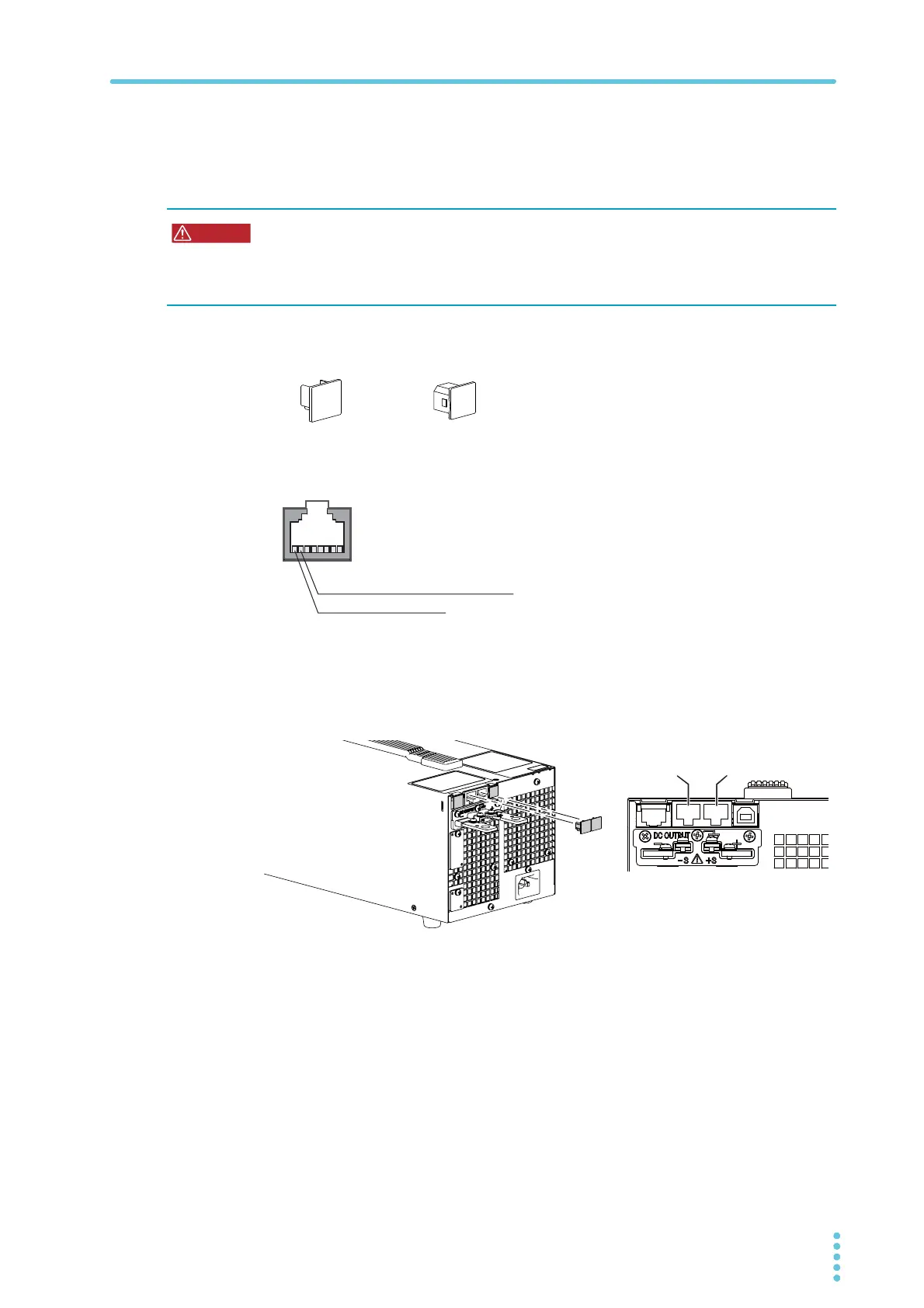
When the PWR-01 is shipped from the factory, con-
nector covers are attached to the communication
connectors as shown in the figure on the left. Keep
connector covers that you remove in a safe place. If
you are not using a connector, attach the connector
cover for safety reasons. If they are damaged or
lost, contact your Kikusui agent or distributor.
The following figure shows the connector pinout when you are facing the rear panel.
1
Check that all PWR-01s that you will connect are turned off.
2
Remove the covers from the RS232C/ TRG IN connector and TRG OUT
connector.
Risk of electric shock.
• Do not touch the communication connectors while the power is turned ON.
• Do not leave the LAN cable connected to the PWR-01 when the other end is not con-
nected.
P1-000-131 P1-000-132
LAN port
RS232C/TRG IN connector
TRG OUT connector
7: TRIG-IN (RS232C/TRIG IN connector)
7: TRIG-OUT (TRIG OUT connector)
8: GND (signal ground)
RS232C/
TRG OUT