Matrix 2360 Programmable Shear User Manual - Section 6
12-092600 A 41
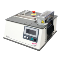
4. Remove the fan from the panel by
removing the four 6-32 flat head
screws. Observe the fan and filter as
you are disassembling it. The fan will
be installed in the new fan panel the
same way. An arrow on the fan shows
the direction of the airflow. It should
flow in, toward the main printed circuit
board. Retain all fan-mounting
hardware in a secure location.
Discard the old fan panel. Check the
filter. Clean it with a vacuum if
needed.
5. Install the old fan into the new fan panel using
the hardware and filter saved from the previous
step. There are now two wire sets attached to
the fan panel and an additional ground wire
attached to the panel itself (not shown). Route
the fan wiring back to the fan power source.
Plug it in to the same J6 connection on the
circuit board where it was connected previously.
6. Take the yellow and green
ground wire attached to
the panel itself (not
shown) and attach it to the
terminal block shown in the
picture at the right. This
block is attached to the
base of the main unit
behind the fan panel. This
grounds the panel.
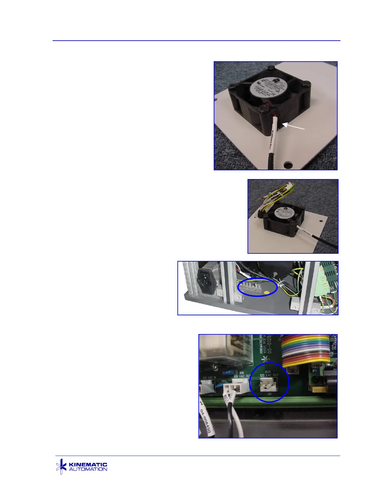
7. Find the connection port at the
bottom of the circuit board labeled
AUX - 120V OUT / J11. Remove
the safety cover on this
connector. Route the cable from
the new socket in the fan panel to
this location. Plug in the
connector with the light blue and
black wires to this port.
Roll Feed Power Connection with Safety Cover Off