ELECTRICAL HAZARD: Disconnect the unit from its power
source before beginning any maintenance or repair procedure. If
a panel is opened, exposure to live electrical circuits is possible.
Failure to follow all electrical safety procedures could result in
SERIOUS INJURY or DEATH BY ELECTROCUTION
CAUTION: Guillotine blades are very sharp, and could cause
SERIOUS INJURY.
Handle the guillotine blades as you would a very sharp knife.
Please be careful.
1. Remove the Blade and Die Block as shown in Sections 7.3 and 7.6.
2. If the drive belt was not already removed, remove the drive belt using
steps 1, 2, and 3 under Replacing the Blade Drive Belt (Section 7.11.1)
and then continue here.
3. Release all pres-
sure applied by
the roller by
loosening the
tension adjustment
knob. See Section
5.1.2.
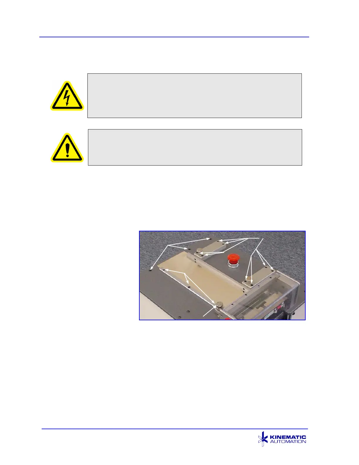
4. Using a 5/32”
Allen wrench,
loosen the eight
10-32 screws that
hold the adjustable guide clamp blocks to the top plate until the blocks can
be lifted about 1.5 mm (0.060”) away from the top plate.
5. Using a 5/32” Allen wrench, loosen the three 10-32 screws that hold the
fixed guide to the top plate. Loosen them enough so that the guide may
be lifted approximately 1.5 mm (0.060”) away from the top plate.
6. Loosen the three socket head screws at the infeed end of the top plate.