Matrix 2360 Programmable Shear User Manual - Section 6
48 12-092600 A
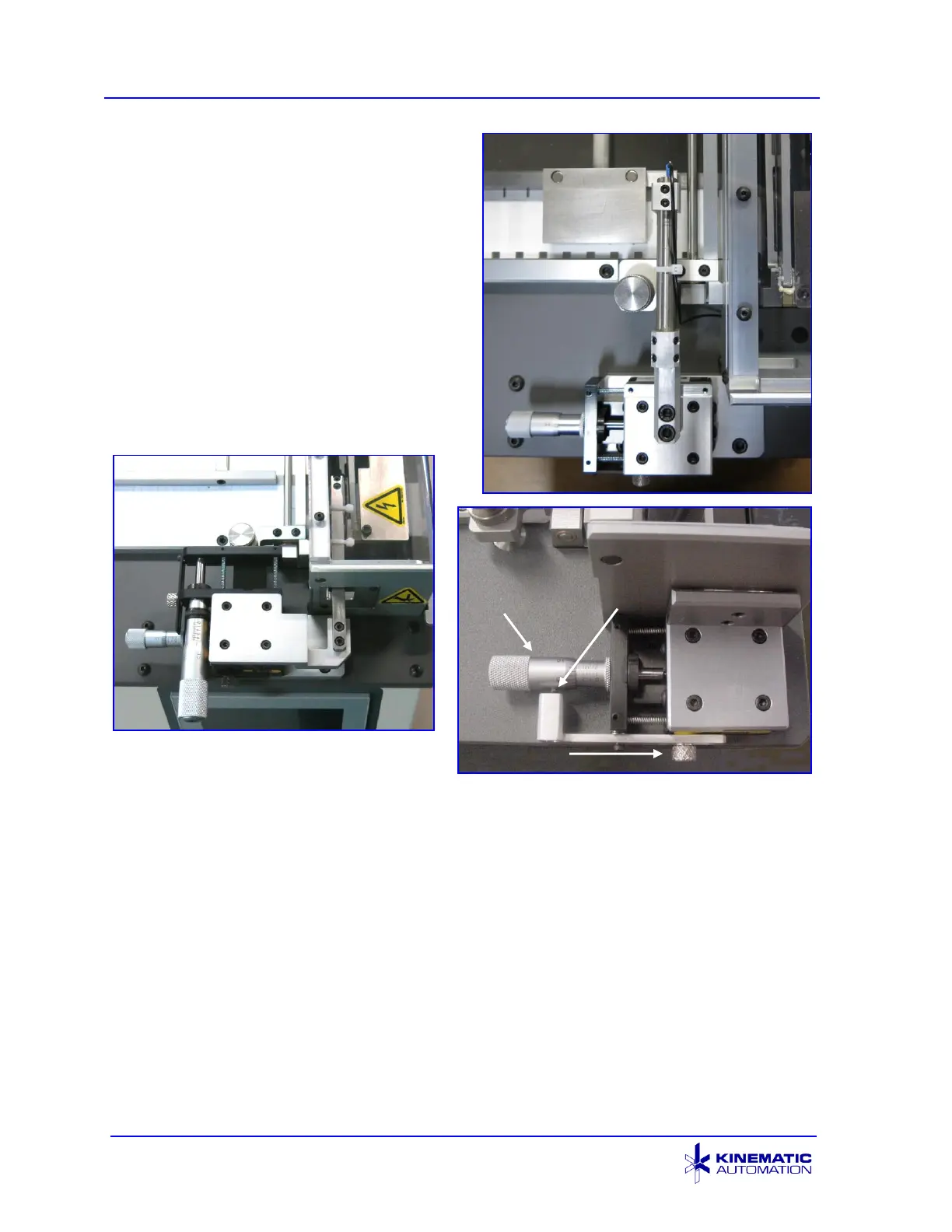
In the illustration at the right, the sensor
support arm is outside of the blade safety
shield.
The lower illustration on the right shows
the micrometer placed in a different
location. In this case, the sensor support
arm goes through the side of the blade
enclosure.
Some units have the sensor arm on a dual
micrometer stage so that the position of
the sensor can be finely adjusted in both
the x and y axes.
Some micrometer-positioning units are
fitted with a barrel pressure ball damper and a knurled nut on a restraining bar.
When adjusting these units, do not release the pressure applied by the ball. The ball
damper only keeps the micrometer barrel from movement caused by the vibration of
the machine. It will not interfere with the adjustment of the micrometer. The
restraining system helps to hold the accurate setting of the micrometer.
6.3.1 Micrometer Adjustments
The micrometer determines where the sensor is located, so it determines where the
cut will be made.
The X-axis micrometer controls the position in the x-axis, the direction of material
travel. It allows positioning the sensor closer to, or farther from, the shear blade.
The x-axis micrometer adjusts how close to the registration feature the cut will be.