Matrix 2360 Programmable Shear User Manual - Section 6
42 12-092600 A
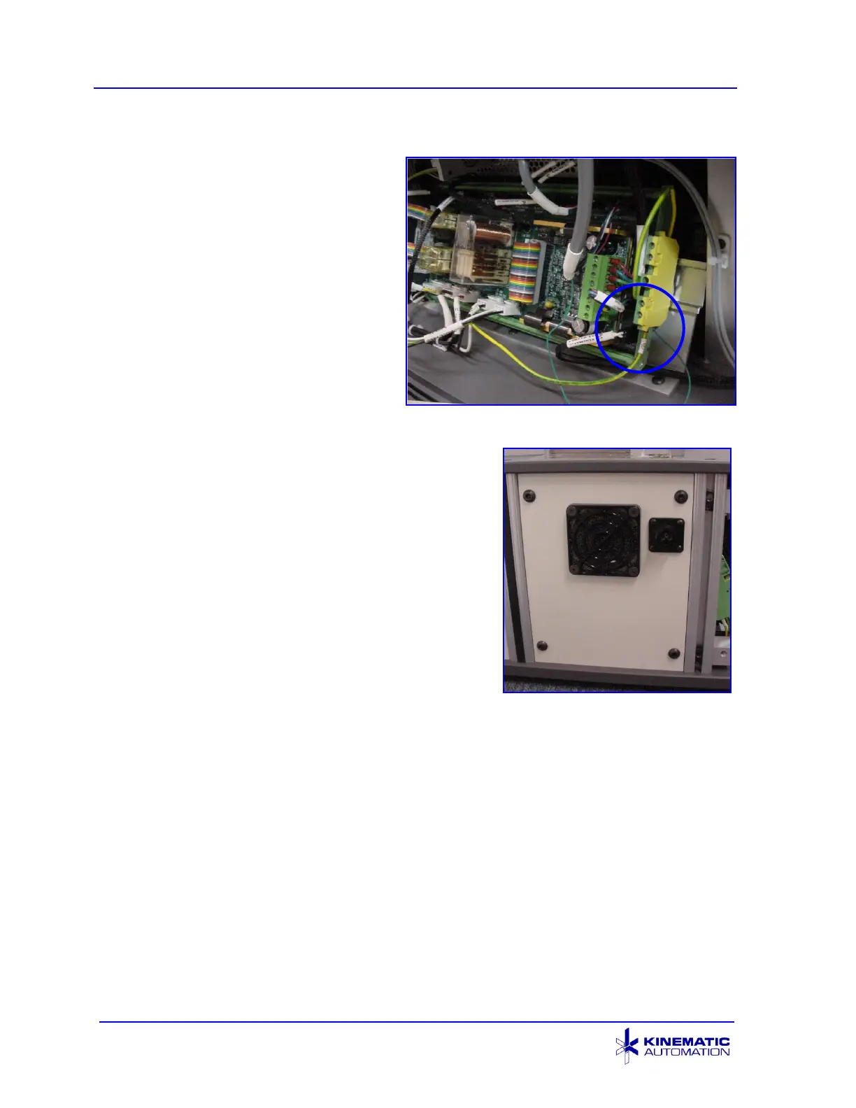
8. Locate the yellow and green
terminal block to the right of the
circuit board. Route the
YELLOW and GREEN (ground)
wire from the new cable to this
location. Move one of the
existing ground wires to the top
of the block if necessary.
Loosen the securing screw with
a small screwdriver, insert the
connector end of the green wire
into the socket, and re-tighten
the screw.
Roll Feed Ground Connection
9. Screw the new fan panel into place using the
saved fan panel hardware. The new power
connection should be in the upper right hand
corner of the fan panel.
10. Remove the two ¼-20 x 0.75” socket head
cap screws in the locations indicated with red
circles in the picture on the next page from
the infeed end of the M2360, using a 3/16”
hex head wrench.
New Fan Panel Installed