Matrix 2360 Programmable Shear User Manual - Section 7
58 12-092600 A
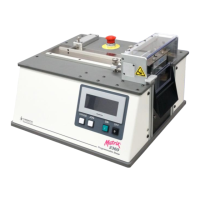
To remove the blade:
1. Lift the safety cover up.
2. If this machine is equipped with the
optional feature registration sensor, be
sure that the sensor support does not
interfere with the blade removal. In
certain circumstances, it may be
necessary to adjust or remove the sensor
support to avoid damage during the blade removal process. Only move this if
the sensor is in the way. Save all removed parts in a secure location for later
reassembly.
NOTE: If it is necessary to adjust the sensor to remove the blade,
be sure to record the micrometer setting prior to adjusting it.
Restore this setting after replacing the blade.
3. Use a
3
/
16
” Hex Key Wrench to loosen the
two ¼-20 screws from the output chute.
These are captive screws so they cannot
be misplaced. Remove the chute.
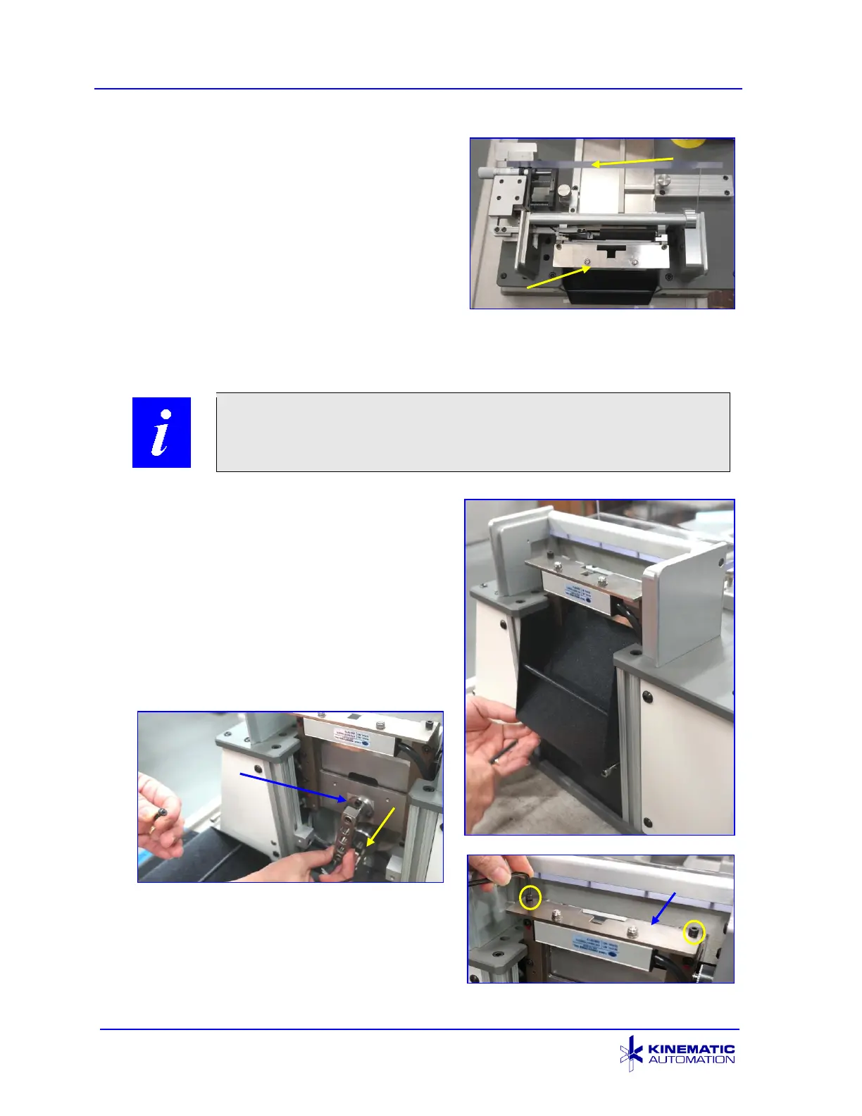
4. With the chute removed, the connecting
bar (Drive Arm) between the motor and
the blade coupling can be removed by
removing the
7
/
64
” screw from the blade
coupler and sliding the bar off the motor
and the blade.
5. The static control bar bracket must be
removed to remove the blade. Use a
9
/
64
” hex key wrench to remove both
screws that connect the bracket to the
die block. Leave the bar power cord
attached; do not pull on it.
static control
bar bracket
optional feature
registration sensor