INFORMATION ABOUT OVERHAULING
8
103
EN
Measure value
A, C, D, E and F
and confront them with
those described in
Tab.8.6
.
If the measured values do not follow those described in
Tab.8.6
, replace connecting rod
T
.
8.5.2 Checking the gudgeon pin-pin axes are parallel
Lubricate gudgeon pin
A
and bearing
R (Fig. 8.12)
.
Insert the gudgeon pin into bearing
R
. Use a dial gauge to
check the axis parallelism of the connecting rod big end
and small end.
Parallel deviation (value V) measured at the tip of the
gudgeonpin, must be a MIN of 0,015 and MAX of 0,030
mm.
If the parallelism values do not comply with the specified
ones,replace the connecting rod with a new one.
8.
5.3
Piston rings check
Insert ring
U
into the cylinder, measure value H (distance
between the points of ring
U
).
Repeat for all the seal rings.
If the measured value H does not correspond to the values
indicated in the table (Tab. 8.7), replace the seal rings U.
Important
•
Seal rings cannot be replaced separately.
NOTE:
refer to
Fig. 8.19
to locate the rings.
Tab. 8.7
Fig 8.14
F
ig 8.15
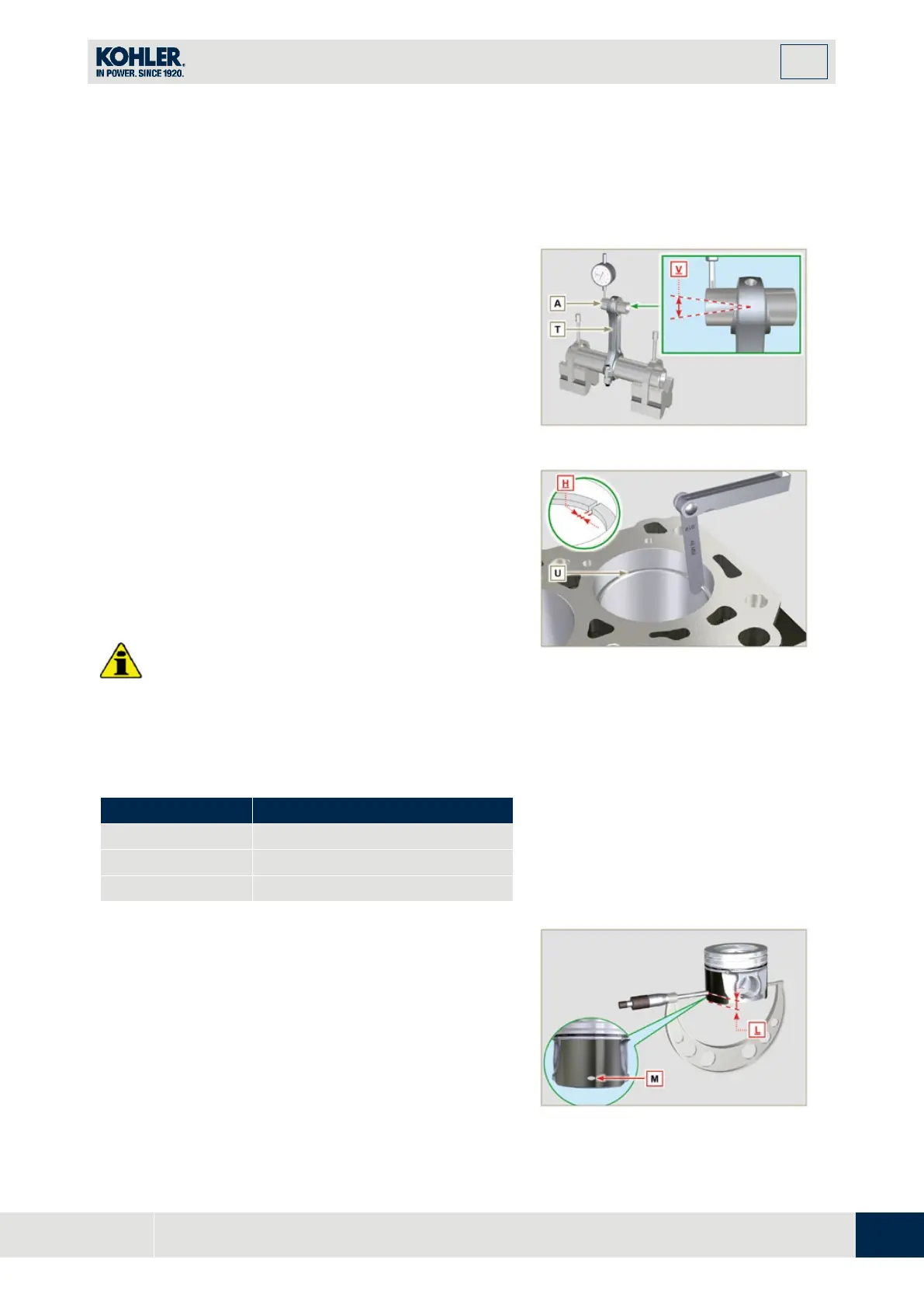
8.5.4 Piston dimension check
Clean the piston thoroughly.
Measure the diameter of the piston at 12 mm (quota
L
) from
the base of the skirt in correspondence with the graphite
lubrication windows
M
.
Refer to
Tab. 8.1b
to establish the clearance value of the
pistons with a decreased diameter.
In correspondence with point
W
, there are:
3 digits for the STD piston;
3 digits followed by R for a piston with an increased
Fig 8.16

 Loading...


