8
INFORMATION ABOUT OVERHAULING
EN 108
Fig. 8.26
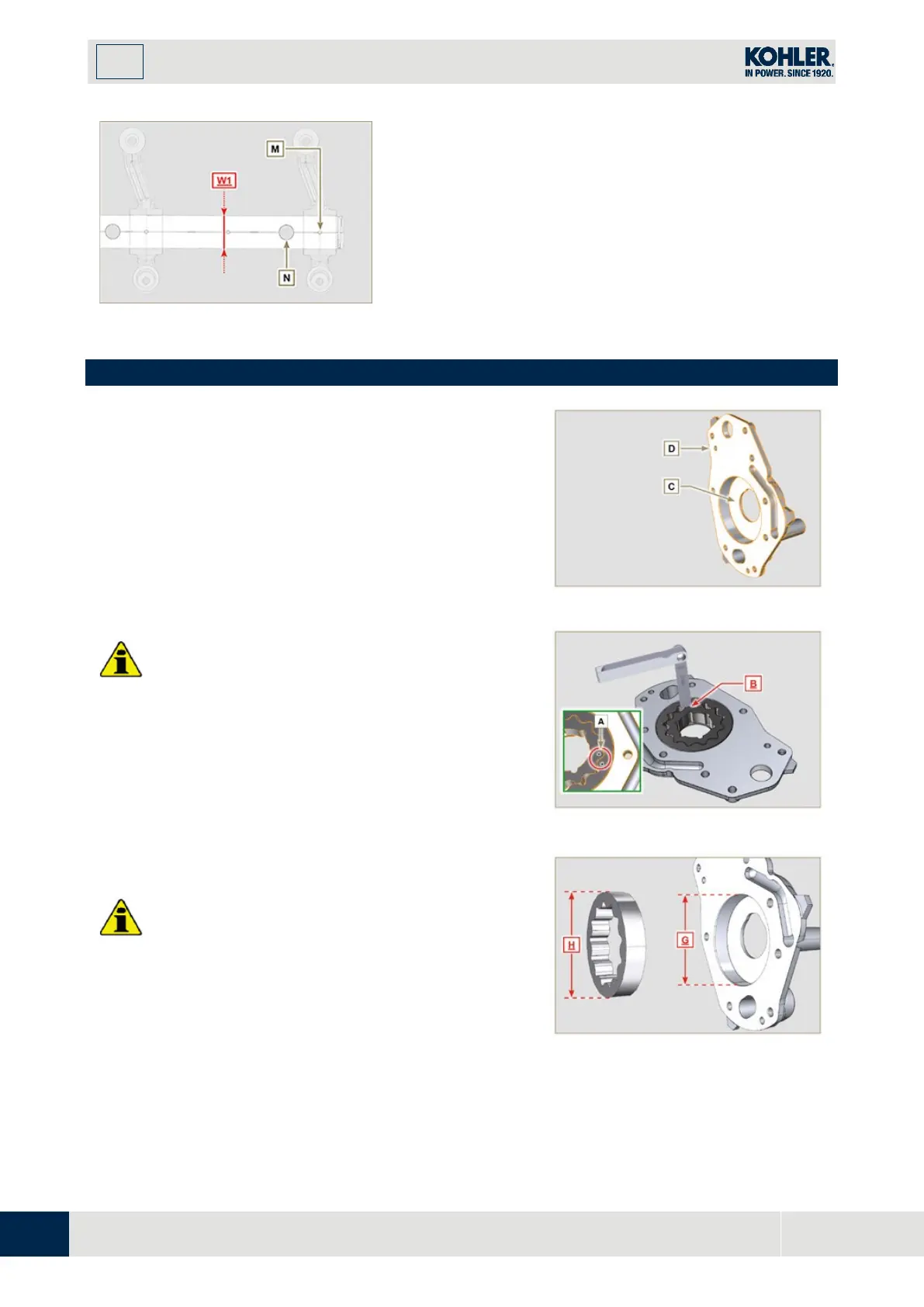
8.7 Oil pump check
8.7.1 Dimensional and visual check
Perform the operations described in
Par.7.8.1 and Par.7.8.4.
Measure clearance value B between the rotor teeth, the
value of allowable wear is MAX 0.28 mm.
Clean all the components thoroughly, check that the work
surfaces C of the rotors and pump body are not worn.
Important
•
Should the results from checks carried out not be i
n
acco
rdance with the conditions described, repl
ace
the timing system carter together with the oil pump.
On assembly, references A must be visible.
Fig 8.28
8.7.2
Check rotors clearance
Important
Replace carter
R
complete with its oil pump, if there are signs
of wear in area
P
of surface
Q (Fig. 8.32 - 8.32a)
.
M
easure values
G and H (Fig. 8.30)
.
Measure values
L, M and N (Fig. 8.31)
.
According to the values measured, calculate the clearance
between
G and H, L and M and L and N
which are to
observe the values in
Tab. 8.13
.
Fig 8.30

 Loading...


