9
ASSEMBLY INFORMATION
EN 134
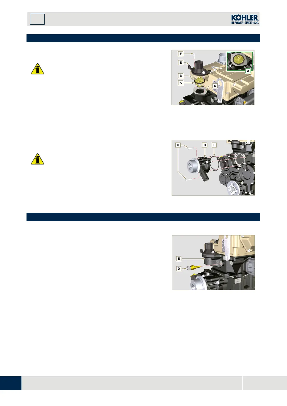
9.13 Coolant circuit assembly
9.13.1 Thermostatic valve
Important
•
Always replace the gasket A after each assembly.
1.
Check the condition of the seal gasket A and fit it o
n
the
thermostatic valve B.
2.
Position the thermostatic valve B in the seat on the
head C (detail D).
3.
Secure the cover E with the screws F on the head C
(tightening torque of 10 Nm).
Fig 9.81
Important
•
Always replace the gasket L every time it is
assembled.
1.
Fit the pump G with the screws H interposing the
gasket L (tightening torque of 25 Nm).
9.14 Electric component assembly
9.14.1 Sensors and switches
9.14.1.1 Coolant temperature sensor
1.
Secure the sensor D onto the head E (tightening
torque of 20 Nm).

 Loading...


